In the input of elements, you can generate and display cross section drawings in the following timeline sections:
- Element
- Glazing
- Hardware
- Additional articles
- Additional data
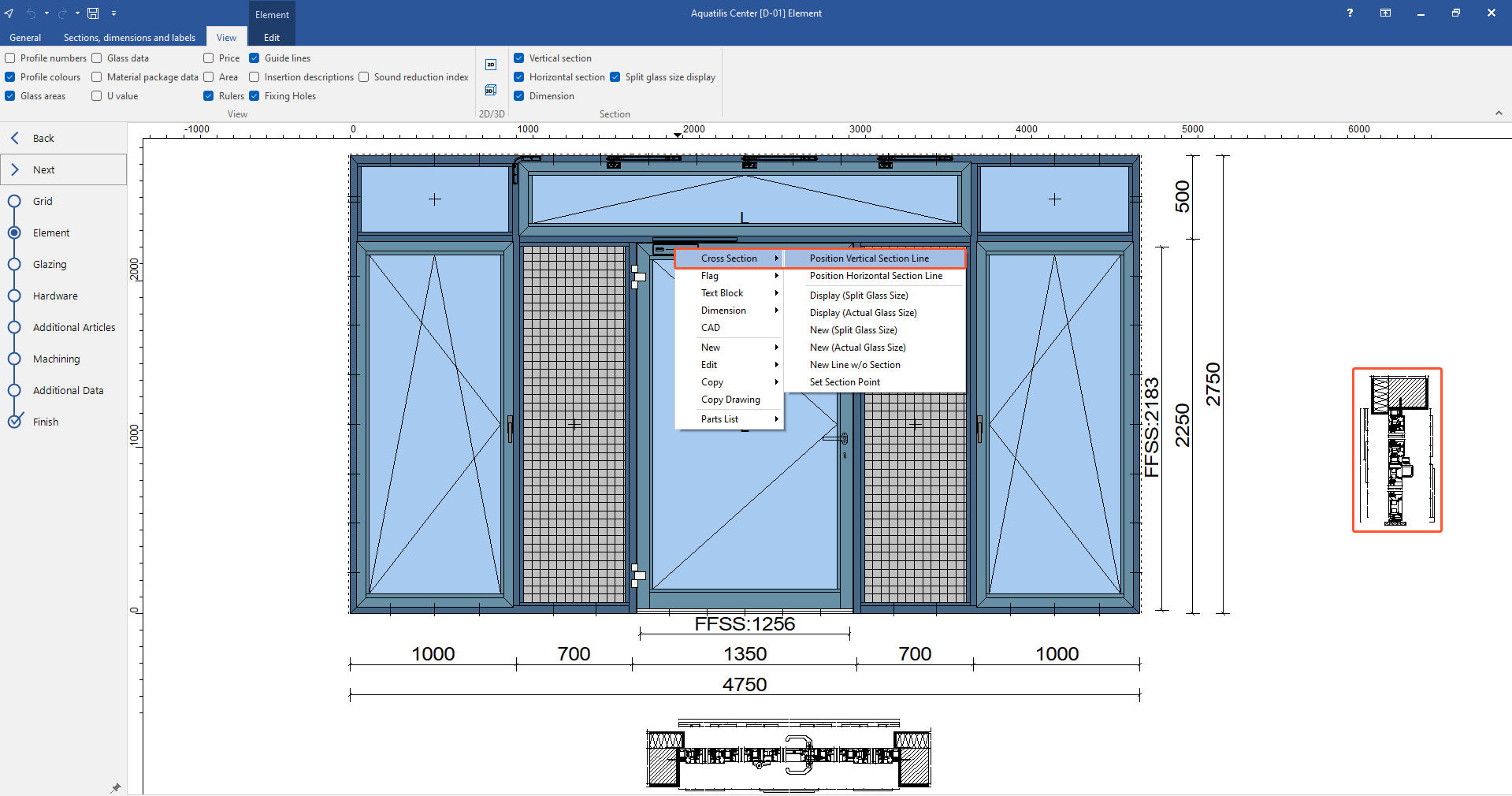
Display section (Split glass size)
- Right-click in the position drawing where the section will begin.
- In the context menu, select "Cross section" > "Display (Split glass size)".
- Draw the section line with the mouse and click the left mouse button to finish. The cross section drawing opens in a new window:
Display section (Actual glass size)
- Right-click in the position drawing where the section line will begin.
- In the context menu, select "Cross section" > "Display (Actual glass size)".
- Draw the section line with the mouse and click the left mouse button to finish. The cross section drawing opens in a new window.
- For doors, you can visualise the opening angle. For this, click the play button or use the slider:
Integrate cross section drawing into position drawing (Split glass size)
- Right-click in the position drawing where the section line will begin.
- In the context menu, select "Cross section" > "New (Split glass size)".
- Draw the section line with the mouse and click the left mouse button to finish.
- Left-click next to the position drawing to place the cross section drawing:
Integrate cross section drawing into position drawing (Actual glass size)
- Right-click in the position drawing where the section line will begin.
- In the context menu, select "Cross section" > "New (Actual glass size)".
- Draw the section line with the mouse and click the left mouse button to finish.
- Left-click next to the position drawing to place the cross section drawing.
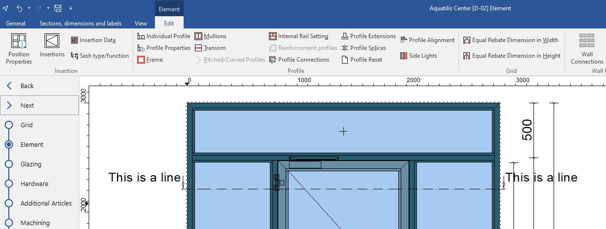
Insert line with text
- Right-click in the position drawing where the section line will begin.
- In the context menu, select "Cross section" > "New line w/o section".
- Draw the section line with the mouse and click the left mouse button to finish.
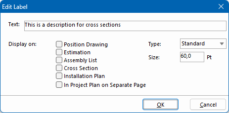
- Enter a text and if necessary, change the font style:
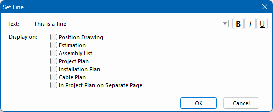
- Select the printouts on which the line and text should appear.
- Confirm the entry with "OK":
Insert section point with label
- Right-click in the position drawing where the section point will be placed.
- In the context menu, select "Cross section" > "Set section point".
- Enter a text:
- Select the printouts on which the line and text should appear.
- Under "Type", select the shape of the label:
- Standard
- Hexagon
- Circle
- If necessary, modify the font size.
- Confirm the entry with "OK".
- Left-click next to the position drawing to place the label.
- Left-click next to the position drawing to place the cross section drawing:
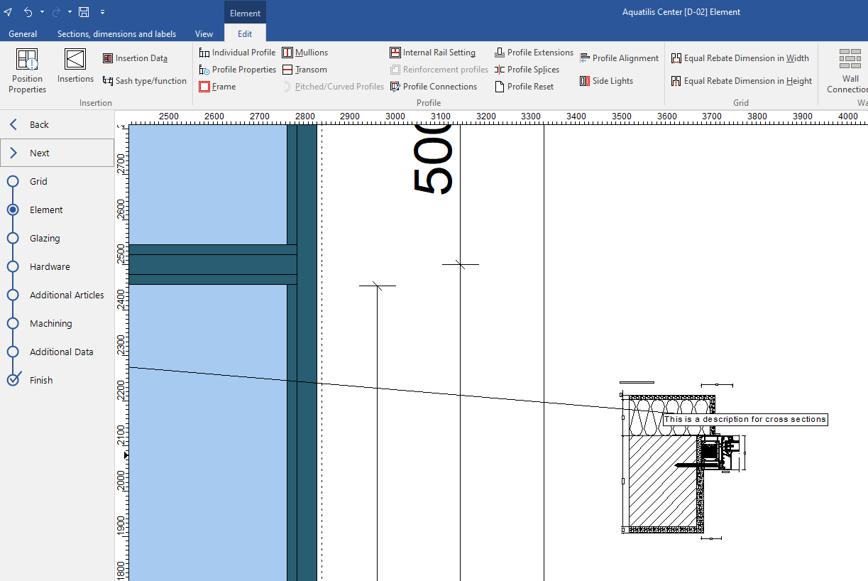
Position vertical section line
Note:
To use this feature, select the "Vertical section" option in the "View" tab.
- Right-click in the position drawing where the section will be placed.
- In the context menu, select "Cross section" > "Position vertical section line":
- The cross section is displayed on the right.
Position horizontal section line
Note:
To use this feature, select the "Horizontal section" option in the "View" tab.
- Right-click in the position drawing where the section will be placed.
- In the context menu, select "Cross section" > "Position horizontal section line":
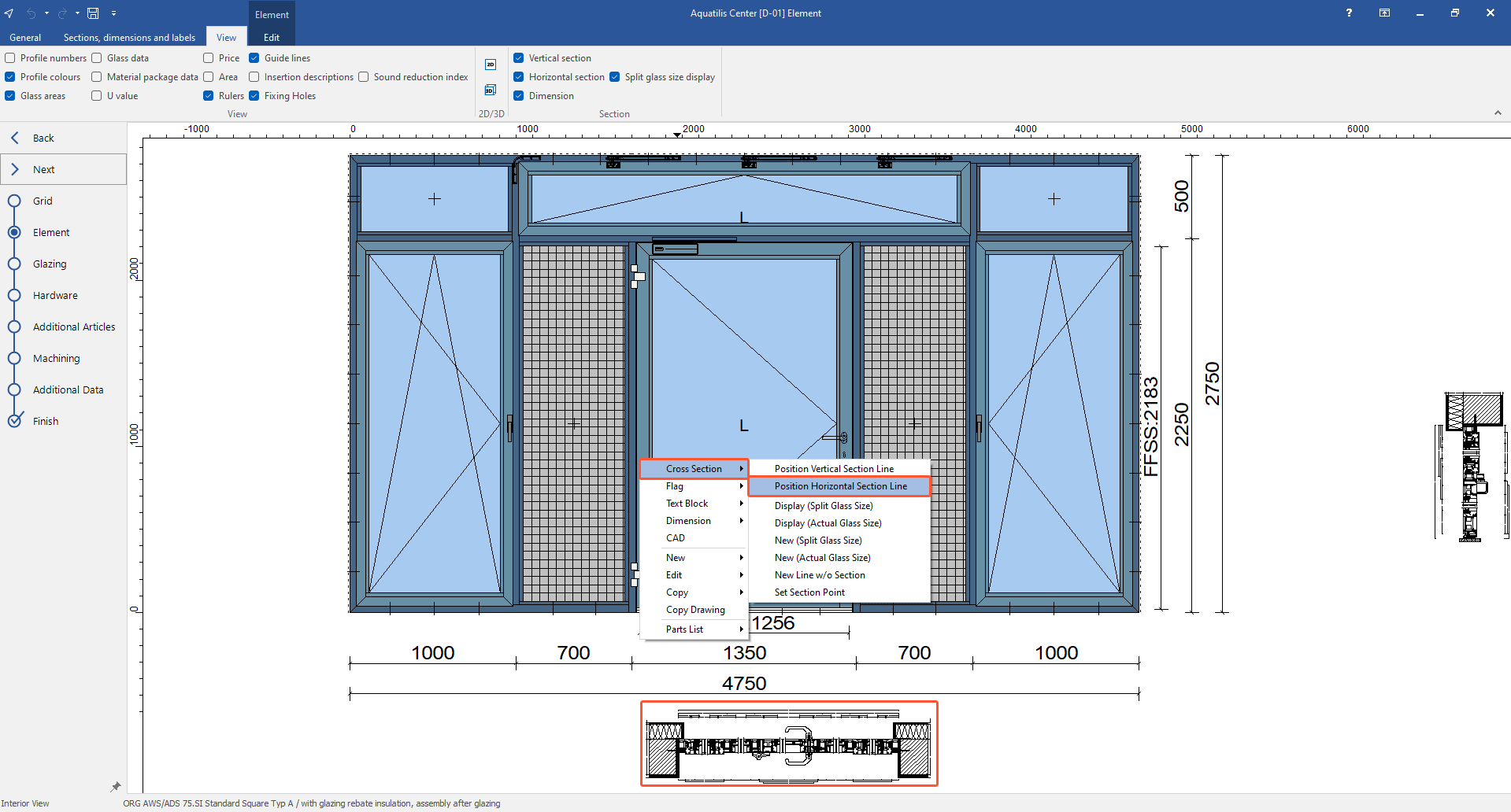
- The cross section is displayed below the position drawing.
Set section line using the ruler
- Open the "View" tab and select the following options:
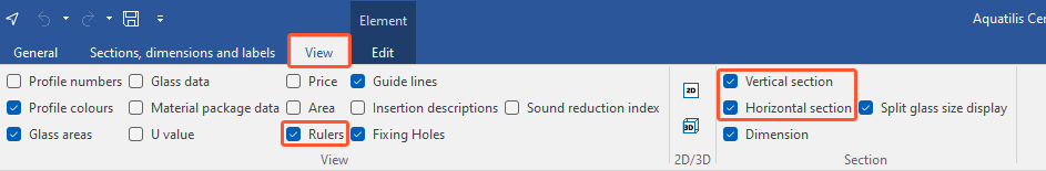
- Rulers
- Vertical section
- Horizontal section
- Click on a point in the upper ruler to display the respective vertical section to the right of the position drawing.
- Click on a point in the left ruler to display the respective horizontal section below the position drawing:
Edit cross section
- Right-click the section line or section drawing you want to edit.
- In the context menu, select "Cross section" > "Edit". In the following window you can make changes.
Delete cross section
- Right-click the section line or section drawing you want to delete.
- In the context menu, select "Cross section" > "Delete".


 Deutsch
 English (UK)
 Français
 Italiano
 Ελληνικά