Display cable plan
- On the home screen, click "Settings" > "Input of elements".
- Open the "Input" tab.
- Select "Display cable plan":
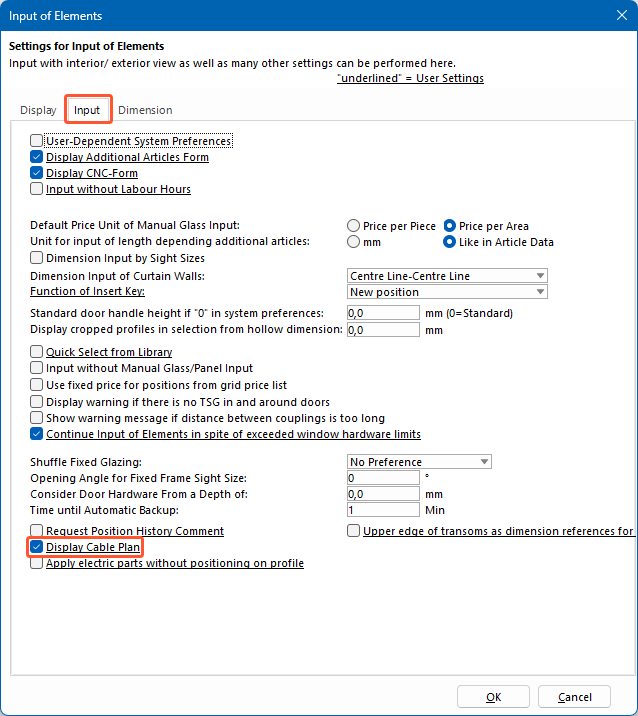
- Click "OK".
Select components
Note:
In the cable plan, you will need at least these three electrical components:
- A consumer, e.g. an electric opener or a motor lock.
- A cable exit from the element. In the case of leaves, a cable insert or contact bridge is required as a passage from the leaf to the frame.
- An external device to supply or control the consumer, e.g. a power supply, key switch, etc.
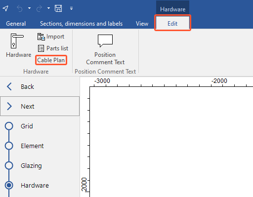
- Open the input of elements.
- In the "Hardware" section, on the "Edit" tab, click "Hardware".
- Select the field where the electronic components will be used.
- Right-click the section "Other hardware":
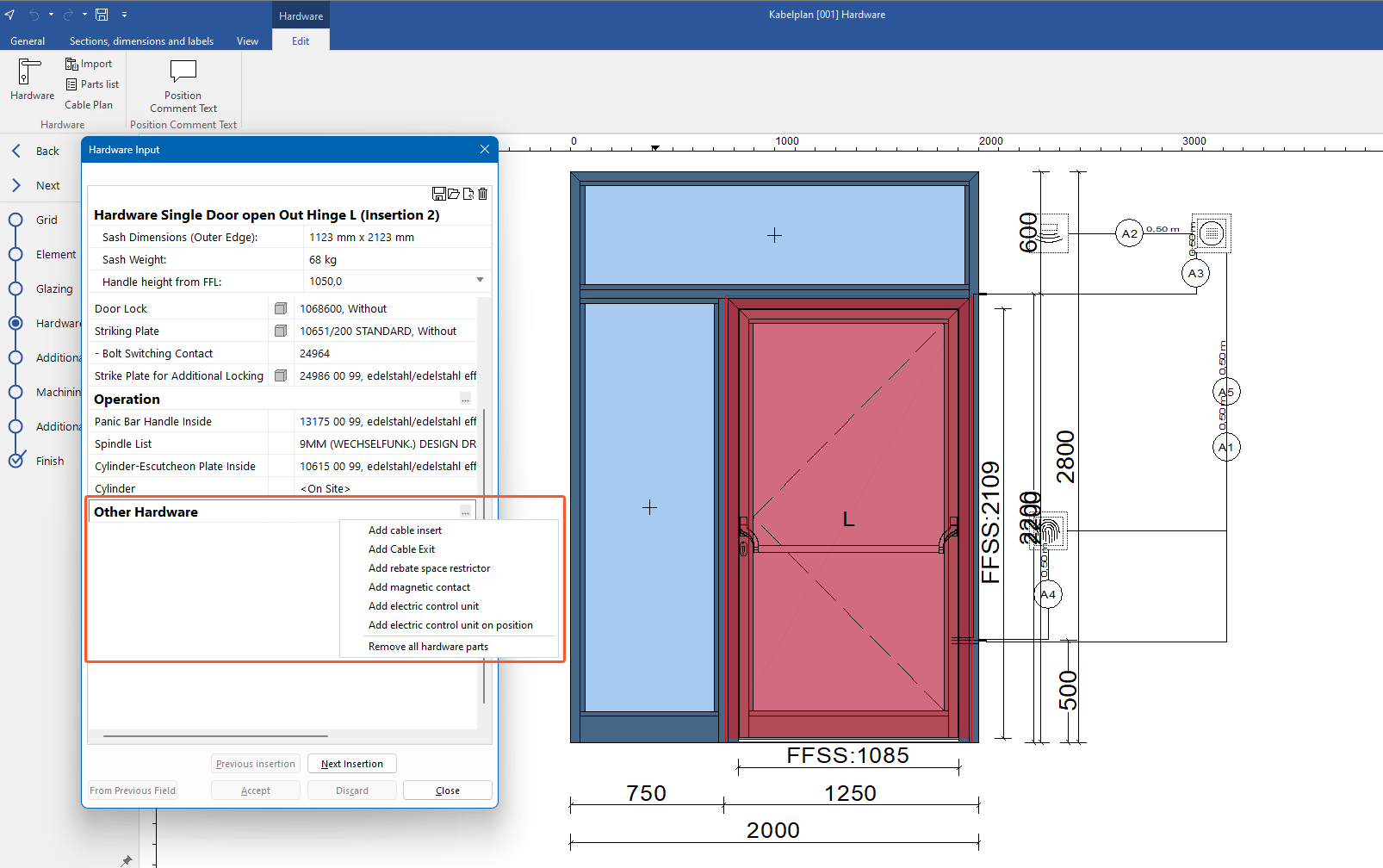
- The following electric components are available in the context menu:
- Cable insert
- Cable exit
- Magnetic contact
- Electric control units (e.g. motion sensors, control units, fingerprint, power supply)
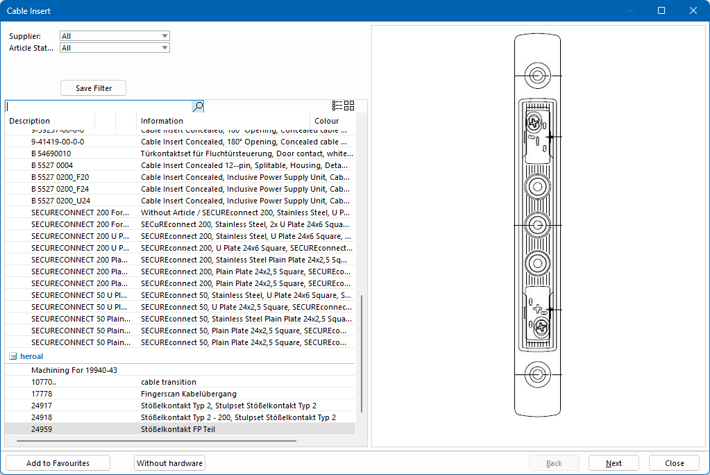
Add cable insert
- Right-click "Other hardware".
- From the context menu, select "Add cable insert".
- Select the required article from the list and click "Next":
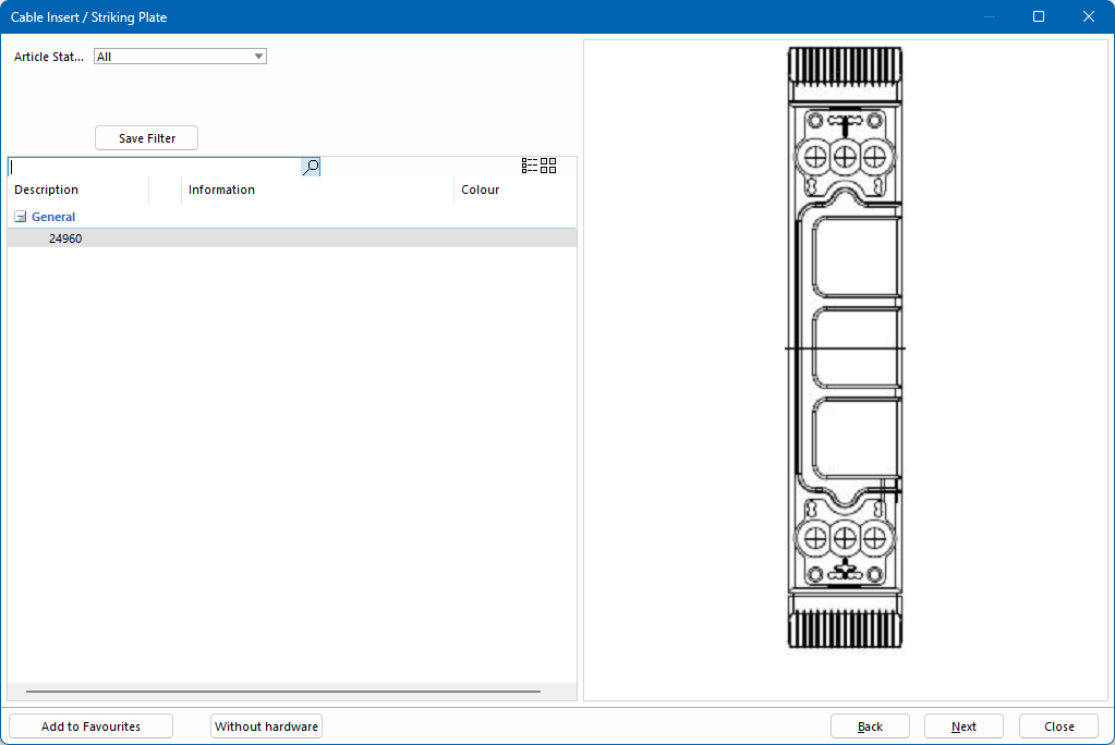
- In the following window, select the striking plate and click "Next":
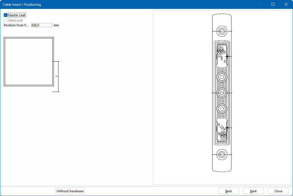
- Define the position of the cable insert:
- Click "Next" to complete the selection.
Add cable exit
- Right-click "Other hardware".
- From the context menu, select "Add cable exit".
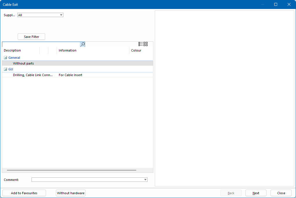
- If available, select an article for the cable exit or select "Without parts" and click "Next":
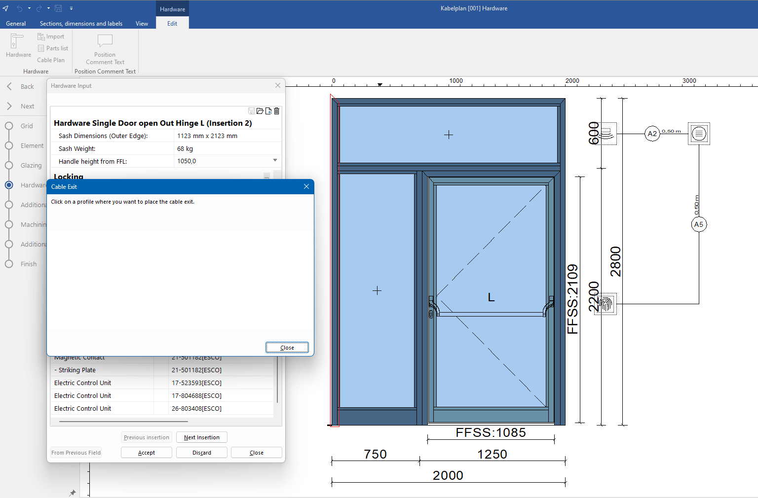
- In the position drawing, click the profile on which you want the cable exit to be positioned:
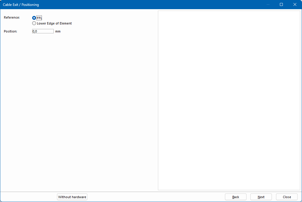
- Define the position of the cable exit:
- Click "Next" to complete the selection.
Add magnetic contact
- Right-click "Other hardware".
- From the context menu, select "Add magnetic contact".
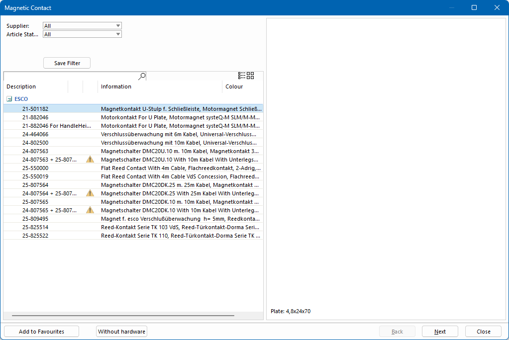
- Select the required article from the list and click "Next":
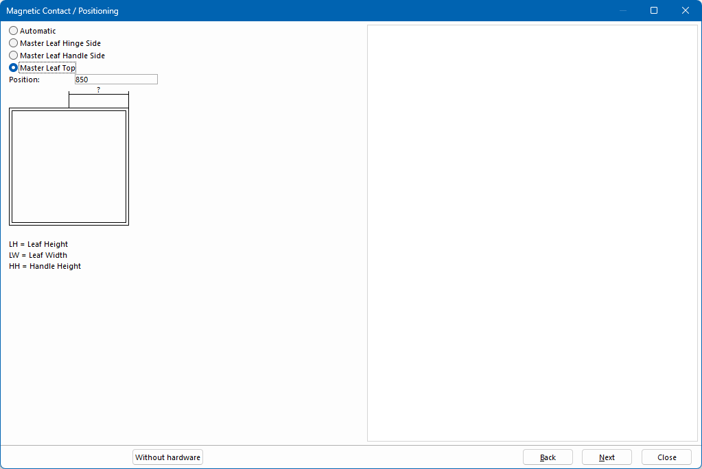
- Define the position of the magnetic contact:
- Click "Next" to complete the selection.
Add electric control unit
- Right-click "Other hardware".
- From the context menu, select "Add electric control unit".
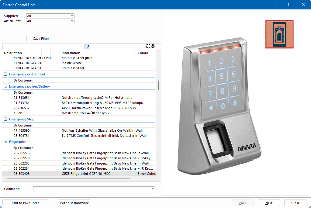
- Select the required article from the list:
- Click "Next".
- Click in the position drawing to position the electric control unit.
- If necessary, select additional options for positioning the electric control unit.
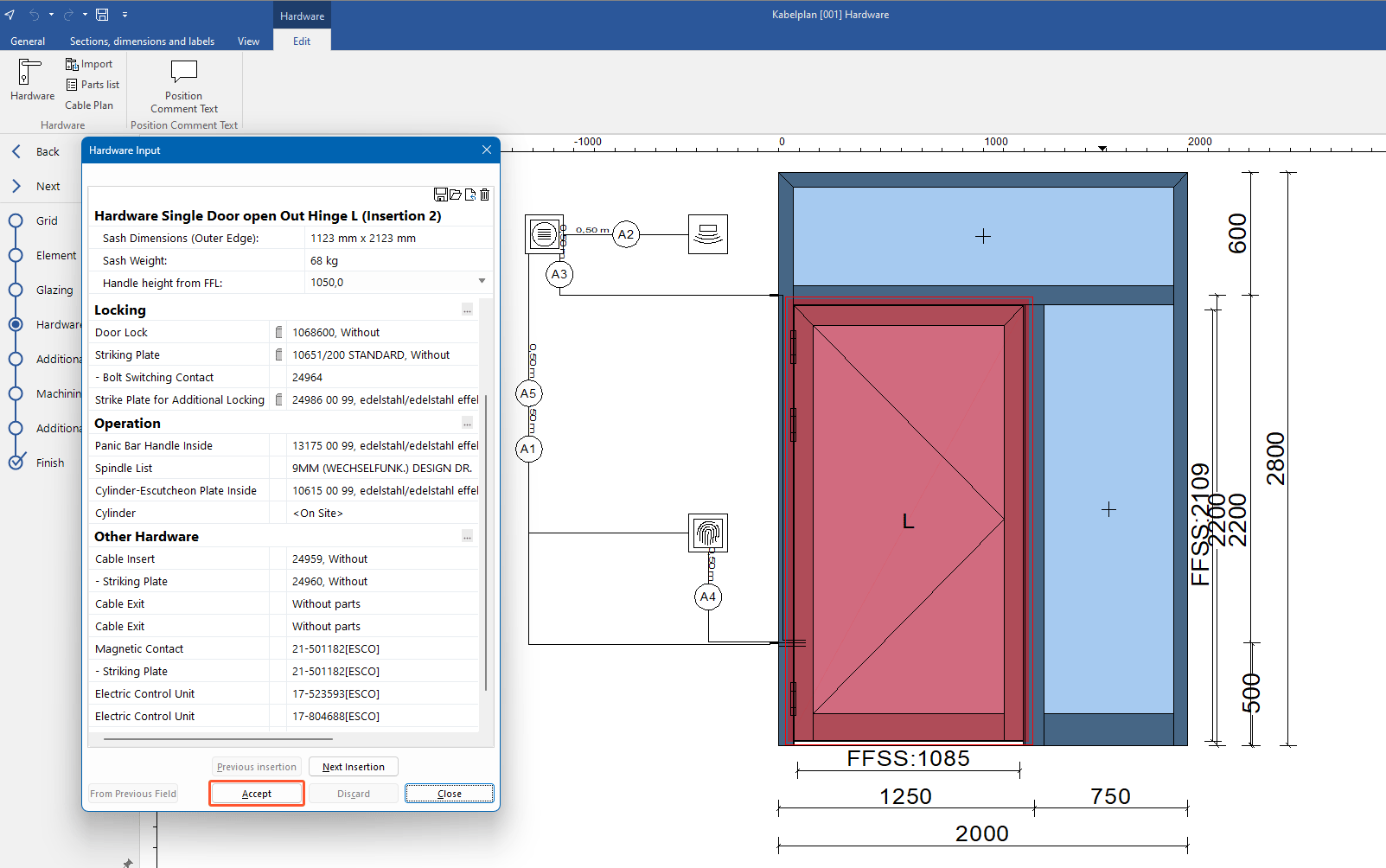
- In the hardware input, click "Accept" to apply the selection:
Symbols in the cable plan
|
Magnet |
Power supply |
Emergency stop |
Emergency power/battery |
Program switch |
Smoke alarm |
Key switch |
Sender / Receiver |
Miscellaneous |
Power plug |
Control unit |
Keyboard |
Switch |
Door terminal |
Distributor |
Video module |


Determine cable route
- In the "Hardware" section, on the "Edit" tab, click "Cable plan":
- In the next window, on the "Start" tab, click "Determine cable route":
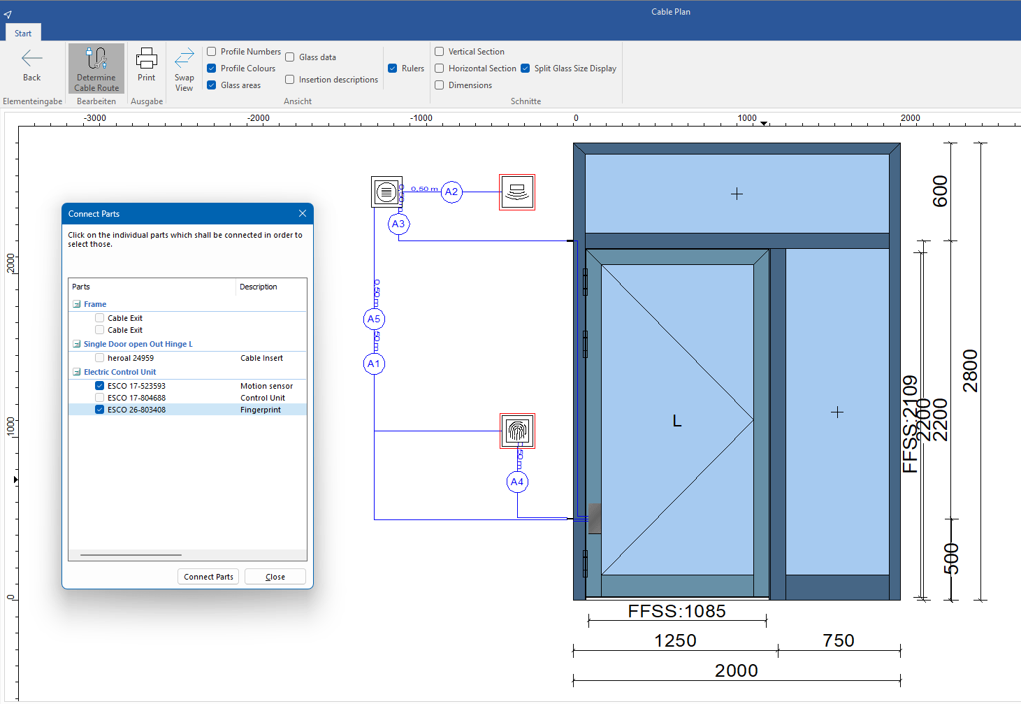
- In the position drawing, click the components to be connected.
- Click "Connect parts" below the parts list.
- In the next window "Cable selection", select a cable type:
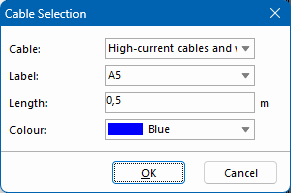
- Enter a label.
- Enter the length of the protrusion.
- Select the colour of the cable on the cable plan.
- Click "OK".
Move components
- In the "Hardware" section, on the "Edit" tab, click "Cable plan".
- In the next window, right-click on the area of the position drawing that you want to move.
- In the context menu, select "Cable route" > "Move":
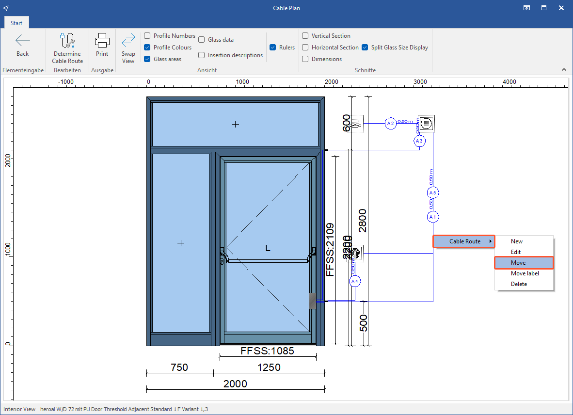
Square symbols are displayed on the cable routes.
- Click on a square symbol and hold down the left mouse button to drag the line to the new position:
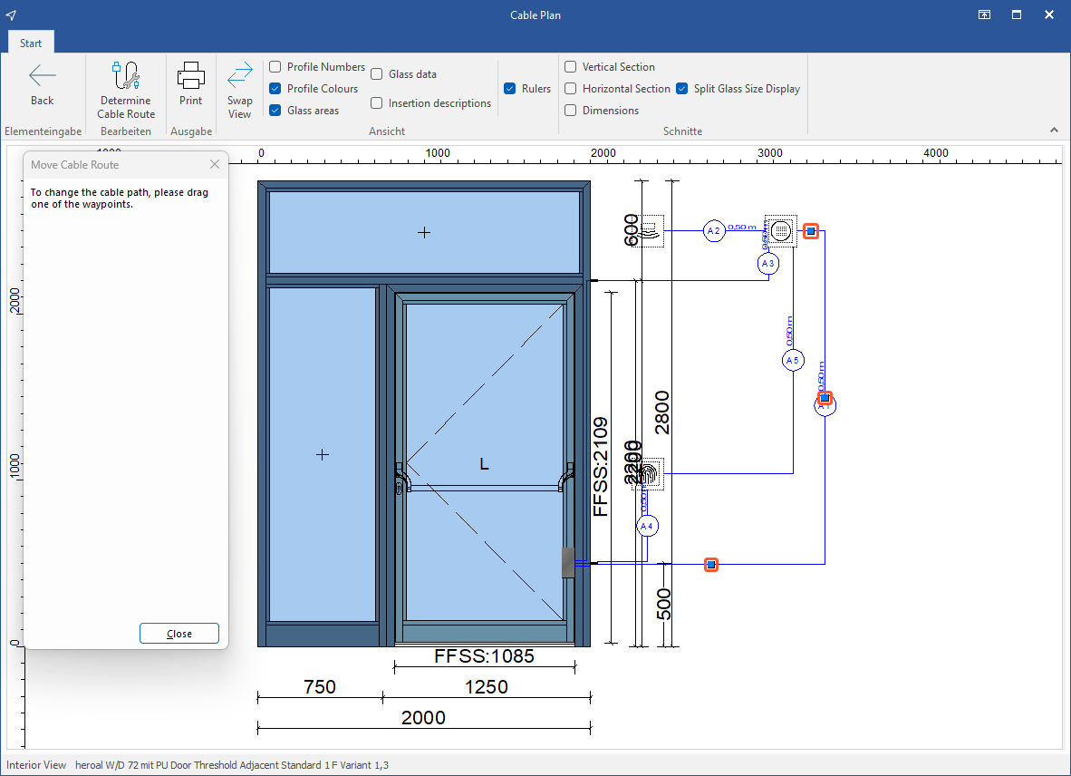
- Click "Close" to complete the process.
Print cable plan
- In the "Hardware" section, on the "Edit" tab, click "Cable plan".
- In the next window, on the ribbon, click "Print":
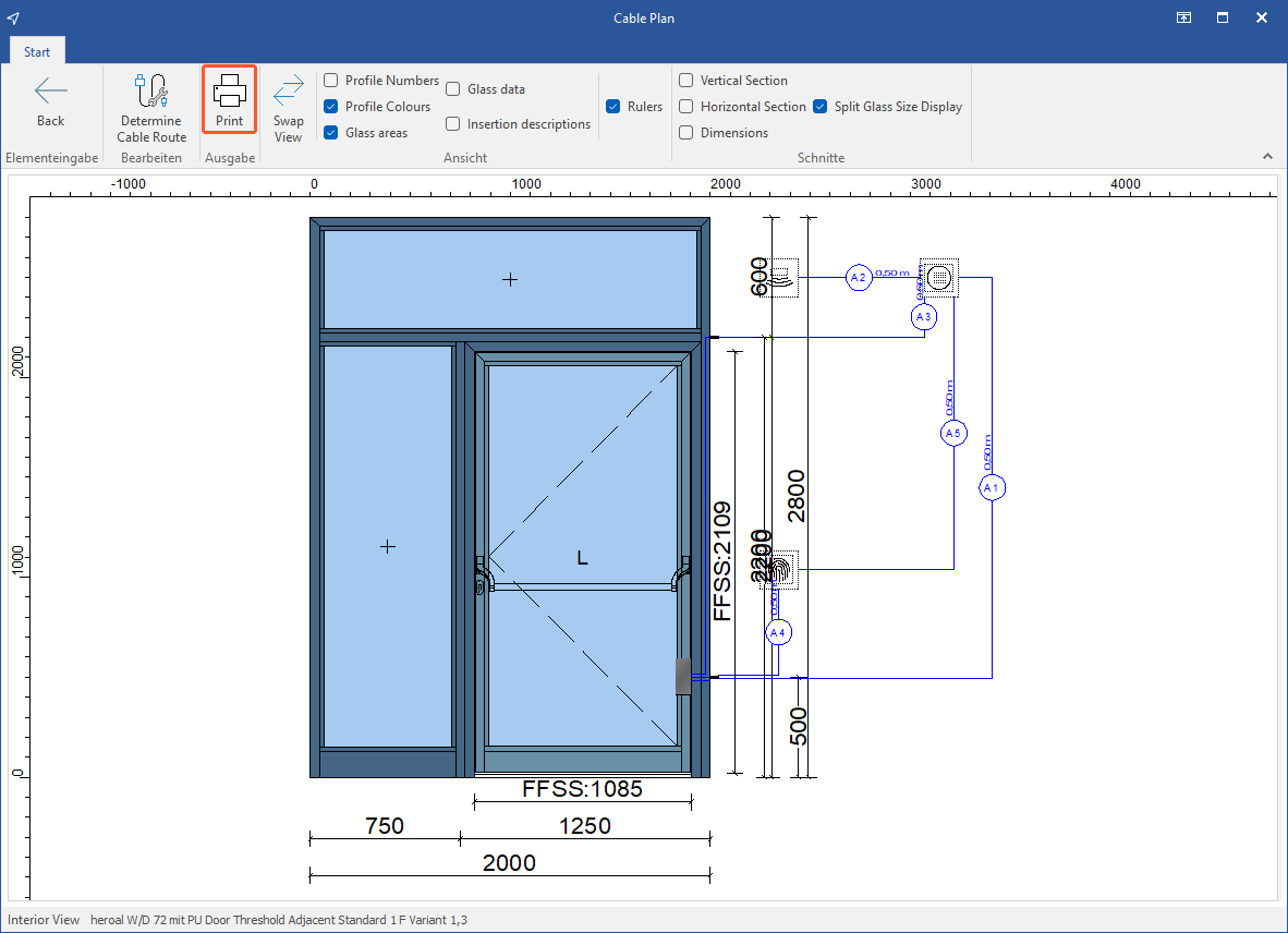
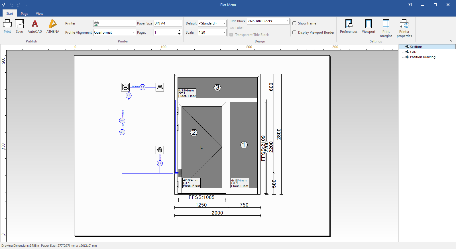
- The cable plan opens in the plot menu:
You can also display cable plans using the "Cable plan" printout. Read "Printouts > Printouts fabrication > Cable plan" for further details.
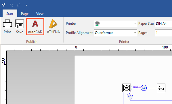
Transfer cable plan to CAD software
- Open the cable plan in the plot menu.
- In the "Publish" group, click the command for the respective CAD software to open the cable plan in the external CAD software:
Enter cable types in the user database
The cable plan distinguishes between two cable plans:
- Valid cable types; e.g. multi-core "bell wires", 230V cables for general use.
- Valid, valid assembled cables used exclusively with electrical components, special or coded plugs; e.g. for motor locks.
In the article data, you can define the cables to be displayed with the corresponding components in the input of element under certain conditions.
- On the home screen, click "User database" > "Article data":
- Select a supplier.
- Click "Add" to create an article. Read "Article data" for further details.
- Under "Article type," select "Cable":
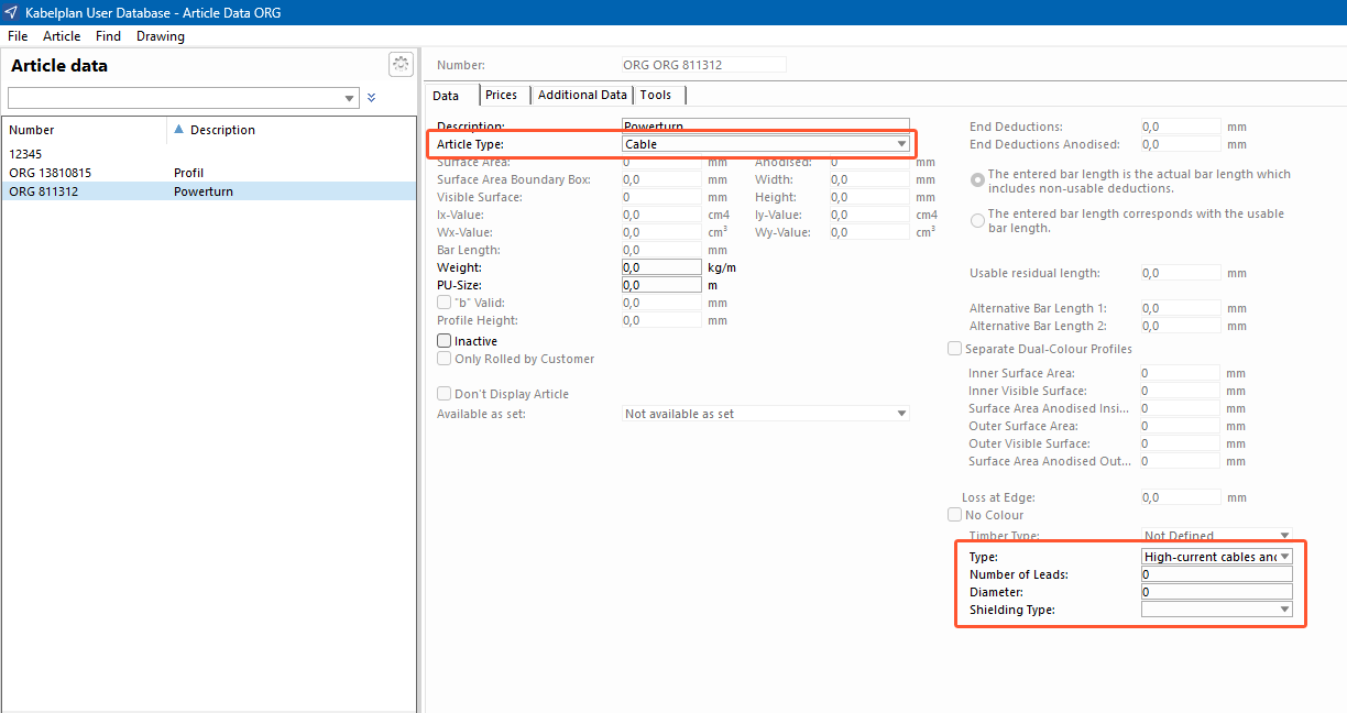
- Under "Type" in the lower-right corner, select one of the following cable types:
- High-current cables and wires (DIN VDE 0250)
- Harmonised cable (DIN VDE 0281/0282)
- Communication cables and wires (DIN VDE 0815/16)
- Under "Number of leads", define the minimum number of wires required for the electric component.
- Under "Diameter", enter the inner diameter of a cable insert or the drilling diameter of a cable exit, for example.
Contact bridges and direct contacts
To define contact bridges and direct contacts for components, such as electric openers, proceed as follows:
- On the home screen, click "User database" > "Door hardware" > "Locks" > "Electric opener".
- Click "Add" to create an article.
- If necessary, select one of the following options:
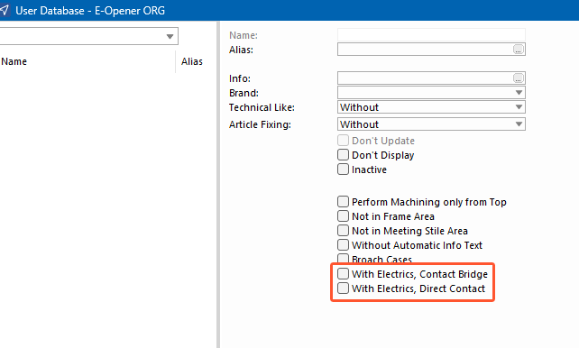
- "With electrics, contact bridge": The power supply is interrupted when the door leaf is opened; e.g. in the case of doors with electric openers in the slave leaf to enable the power supply of the electric opener.
- "With electrics, direct contact": The power supply is not interrupted when the door leaf is opened; e.g. in the case of doors with motor locks in order to evaluate the control and evaluation of the lock states.


 Deutsch
 English (UK)
 Français