With the "Fixing holes" feature, you can insert machining for wall connections directly in the input of elements and without complex macro programming.
Display fixing holes in the position drawing
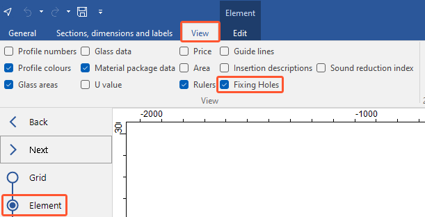
- In the input of elements, click the "View" tab.
- Select the "Fixing holes" option:
Automatic fixing positioning
The automatic fixing positioning determines the positioning for the frame holes per field according to your specifications. The positioning of the holes is automatically updated as soon as the element is edited.
- Open a position.
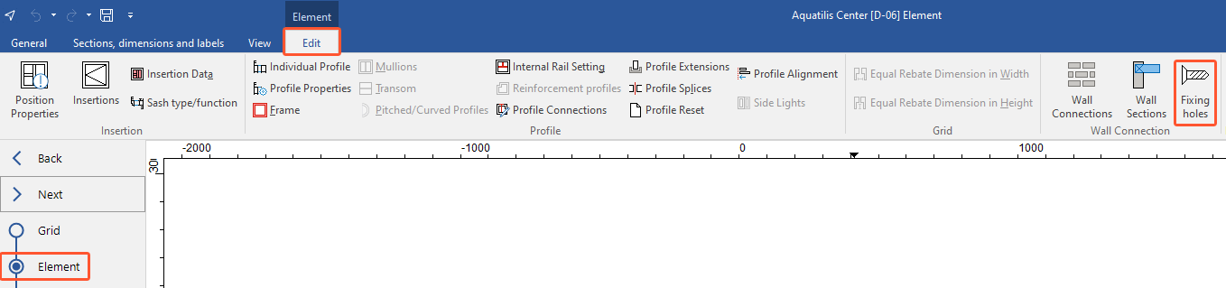
- In the "Element" section, on the "Edit" tab, click "Fixing holes":
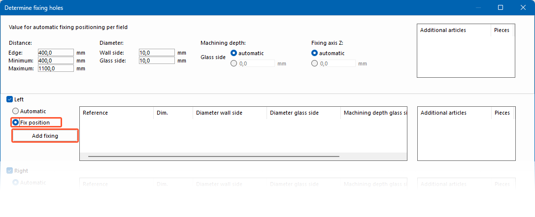
- In the top section (1) of the next window, enter the values for the automatic fixing positioning per field:
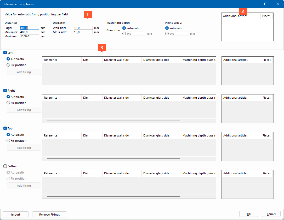
- Distance to edge
- Minimum distance between fixing holes
- Maximum distance between fixing holes
- Diameter wall side
- Diameter glass side
- Machining depth glass side
- Fixing axis Z
- Right-click in the top field "Additional articles" (2) and select "New".
- In the next window, select the additional articles that are required per fixing hole and enter the number of pieces. Click "OK".
- Right-click the added additional article to edit, delete, cut, or copy it.
- In the bottom area (3), select the frame sides for which you want to determine fixing holes and select the "Automatic" option for each side.
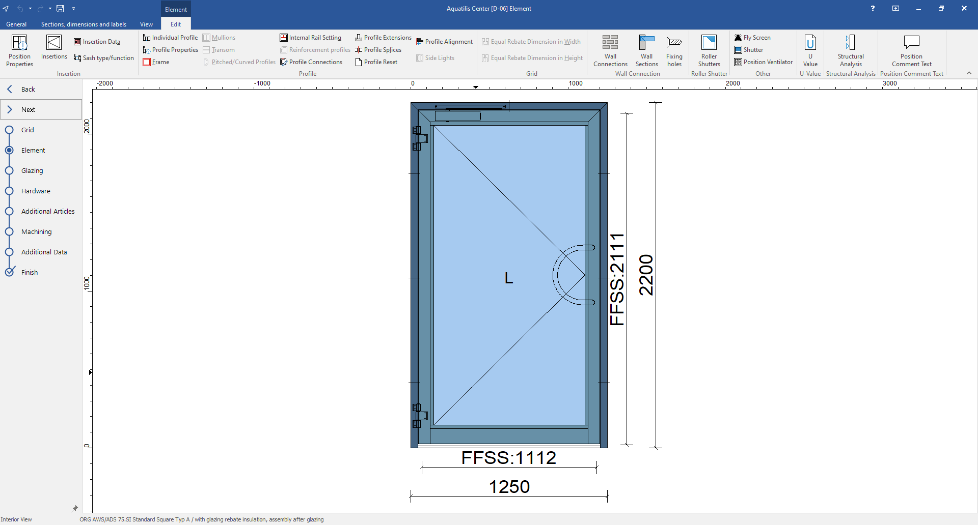
- In the "Determine fixing holes" window, click "OK". The automatically determined fixing holes are displayed in the position drawing:
Note:
If there is already other machining on the frame of the element that overlaps with the automatically determined fixing holes, they must be moved manually in the "Determine fixing holes" window or in the "Machining" section.
Adjust fixing holes
Fixing holes can also be adjusted for single frame sides independently of the automatic specifications.
- Open a position.
- In the "Element" section, on the "Edit" tab, click "Fixing holes".
- In the bottom section, select the frame sides for which you want to determine fixing holes and select "Fix position" for the side you want to adjust:
- Selected sides for which the "Automatic" option is selected are determined as described in the "Automatic fixing positioning" paragraph.
- Below the side selection, click "Add fixing".
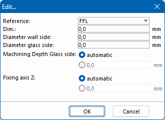
- In the next window, select the reference:
- FFL
- Top (Outer element dimension)
- Bottom (Outer element dimension)
- Left (Outer element dimension)
- Right (Outer element dimension)
- Below that, enter the values for the fixing hole positioning:
- Dimension
- Diameter wall side
- Diameter glass side
- Machining depth glass side
- Fixing axis Z
- Click "OK". The data of the fixing hole positioning is displayed in the list. Right-click the entry to edit, delete, cut, or copy the data.
- Right-click in the "Additional articles" field next to it and select "New ".
- In the next window, select the additional articles that are required per fixing hole and enter the number of pieces. Click "OK".
- Right-click the added additional article to edit, delete, cut, or copy it.
- In the "Determine fixing holes" window, click "OK". The manually defined fixing holes are displayed in the position drawing.
View of machining
- Open an element with fixing holes in the input of elements.
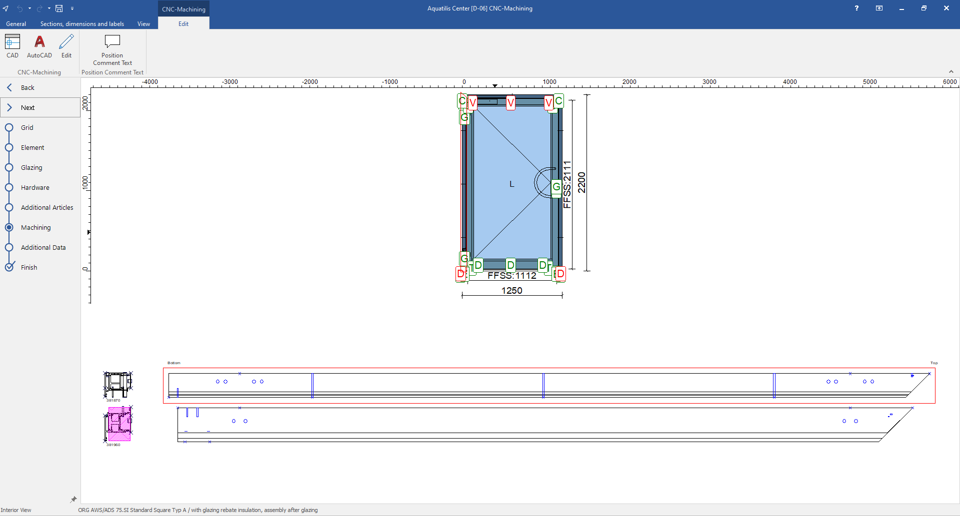
- Open the "Machining" section.
- Click on a profile with fixing holes. The fixing holes are displayed in the cross section of the profile:
- Double-click on the profile drawing to get a view in 3D. On the left side, you the group with the fixing holes is displayed:
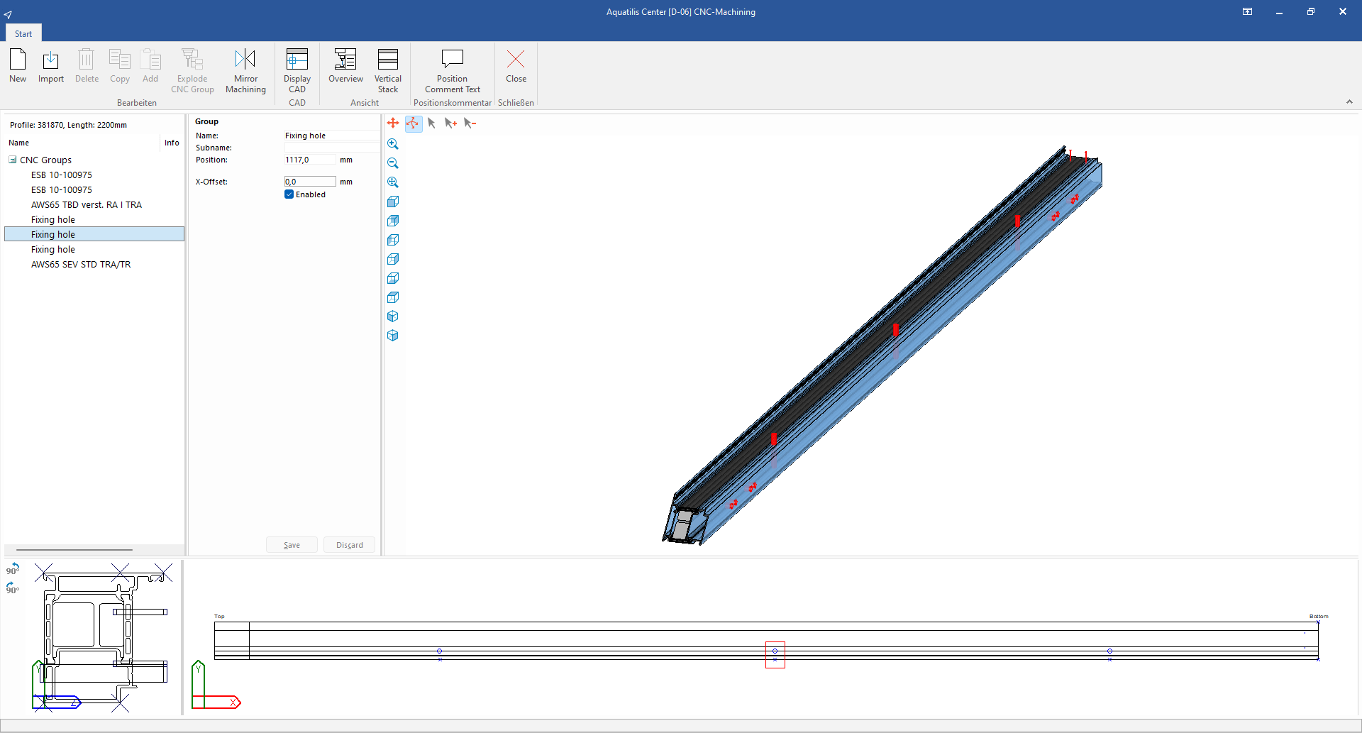
- If a fixing hole overlaps with other machining, enter a value under "X-Offset" to move the fixing hole.
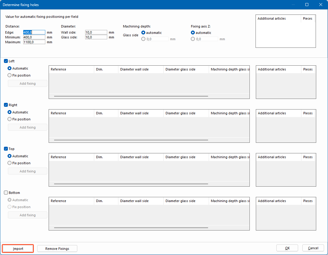
Import
- Open a position.
- In the "Element" section, on the "Edit" tab, click "Fixing holes".
- Click "Import" to apply the values of the automatic fixing hole positioning, as well as manually defined fixing holes from another position:
- In the next window, select the project and then the position from which you want to transfer the fixing holes.
- In the "Determine fixing holes" window, click "OK". The manually defined fixing holes are displayed in the position drawing.
Global preferences
Values for automatic fixing hole positioning can be set globally for all users.
- On the home screen, click "Settings" > "Additional settings" > "Fixing holes":
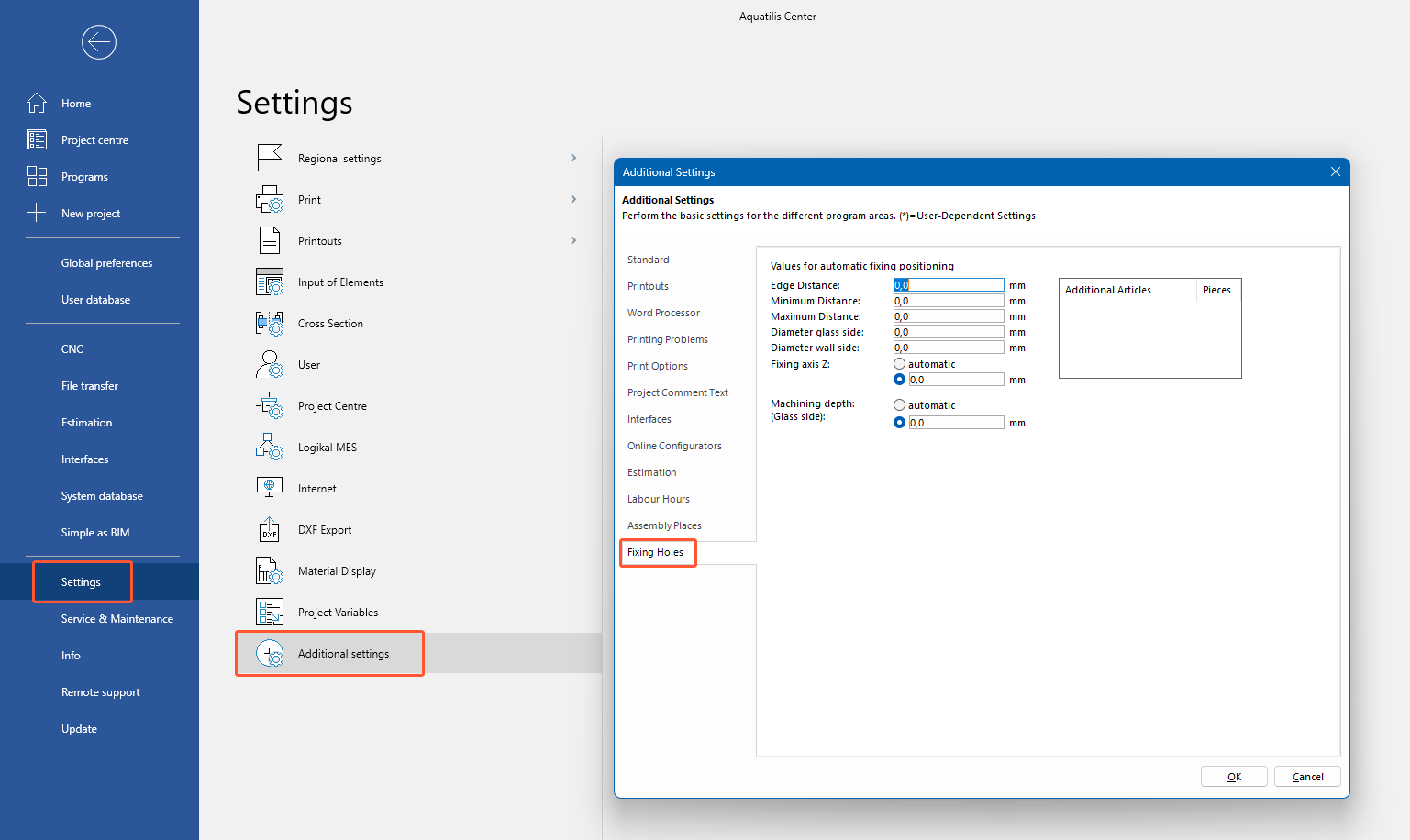
- Enter the values for the automatic fixing hole positioning:
- Edge distance
- Minimum distance between fixing holes
- Maximum distance between fixing holes
- Diameter glass side
- Diameter wall side
- Fixing axis Z
- Machining depth (Glass side)
- Right-click in the "Additional articles" field and select "New ".
- In the next window, select the additional articles that are required per fixing hole and enter the number of pieces. Click "OK".
- Right-click the added additional article to edit, delete, cut, or copy it.
- In the "Additional settings" window, click "OK". The specified values are displayed for each position in the "Determine fixing holes" window, where they can be individually adjusted for the position.
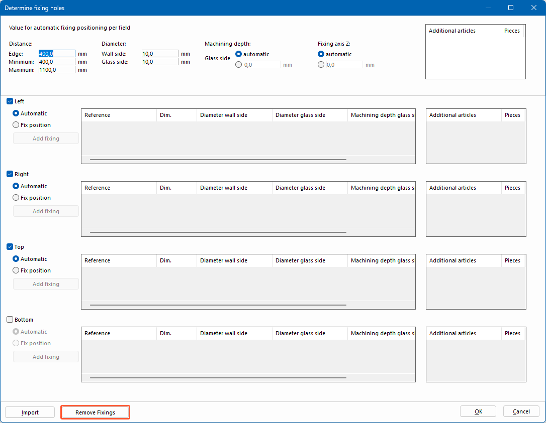
Remove fixing holes
- Open a position with fixing holes.
- In the "Element" section, on the "Edit" tab, click "Fixing holes".
- Click "Remove fixings" to remove all fixing holes from the position:


 Deutsch
 English (UK)
 Français