Hardware selection is similarly to the selection in the Input of Elements. The software asks about the connected components in logical order, one after the other. This ensures that everything is included; no components will be forgotten. This new way of entering the hardware also provides a clearer overview and offers improved user friendliness.
Hardware Selection Layout
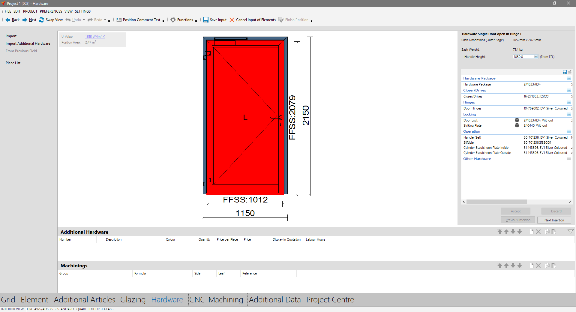
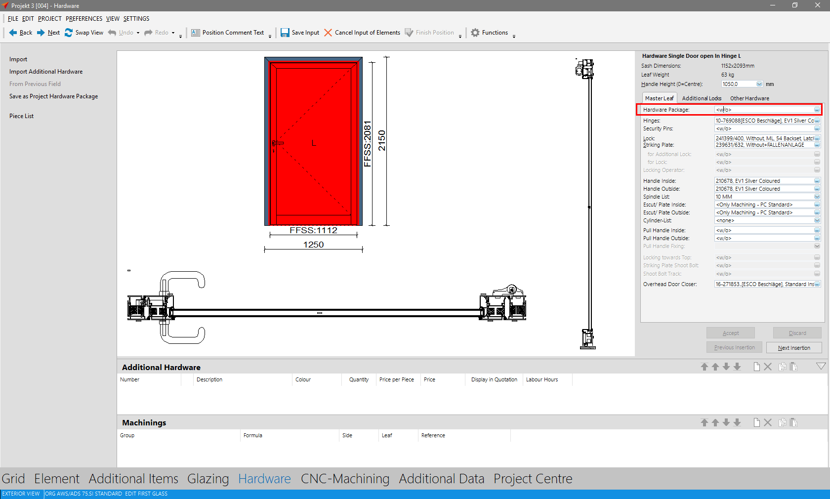
In the program window for entering the hardware, the list of hardware on the right has been restructured. All used articles are clearly and logically listed by category.
Saving and Loading the Hardware Selection
The two new icons on the right above the item list allows you to save your hardware selection globally for the project and use it again for other positions.
This replaces the "Project hardware package" function from earlier Logikal versions.
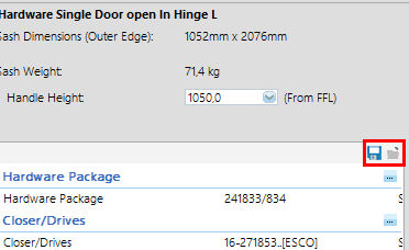
Click on the disk icon to save your selection. A new program window will open. Under "Configuration Name," enter the designation that you wish to save with the selection.
Click on the folder icon to add your hardware selection to a position.
Hardware Item View
There are two small icons on the right above each hardware selection.
![]()
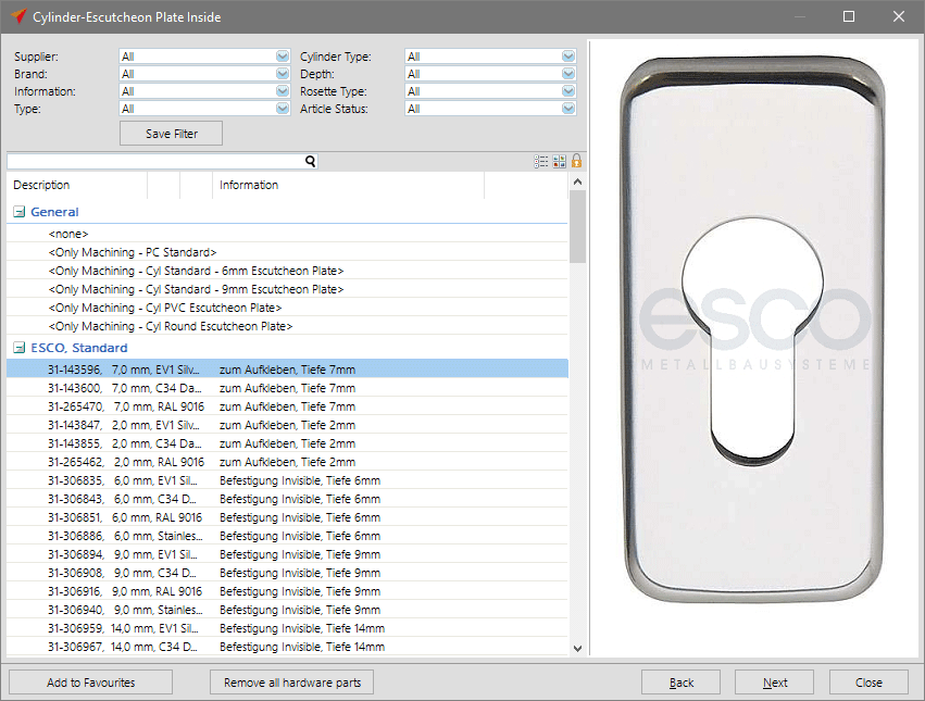
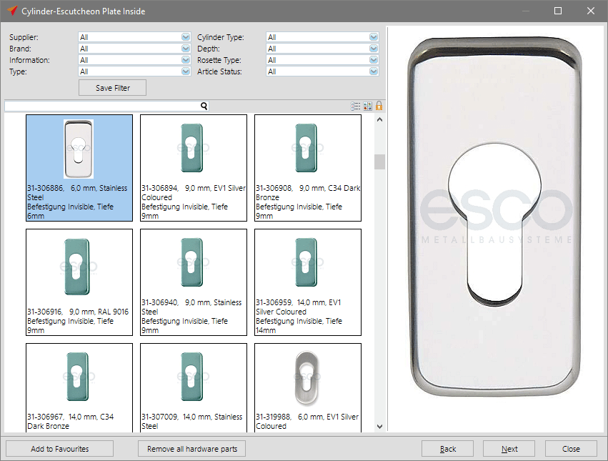
These allow you to toggle between list view and icon view.
List view example
Icon view example
Modify Items from Hardware Packages
If Logikal displays a package icon behind an article, this means that this article was specified in a hardware package selected by you.
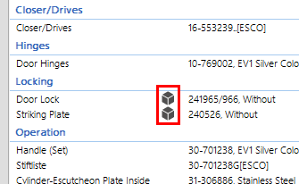
If the package is displayed in gray, you cannot change the article.
If the package is blue, you can modify the article.
Selecting Hardware
When selecting the hardware, the software will query the connected components in a logical order, one by one.
An assistant will guide you through the entire inputting process.
The new program version features additional filter options.
These are located in the upper area of the respective component.
This means selecting articles is now even easier and more error-proof.
You can save your filter settings for the next use.

Positioning Components
Components are selected as before, from an overview list that includes a preview.
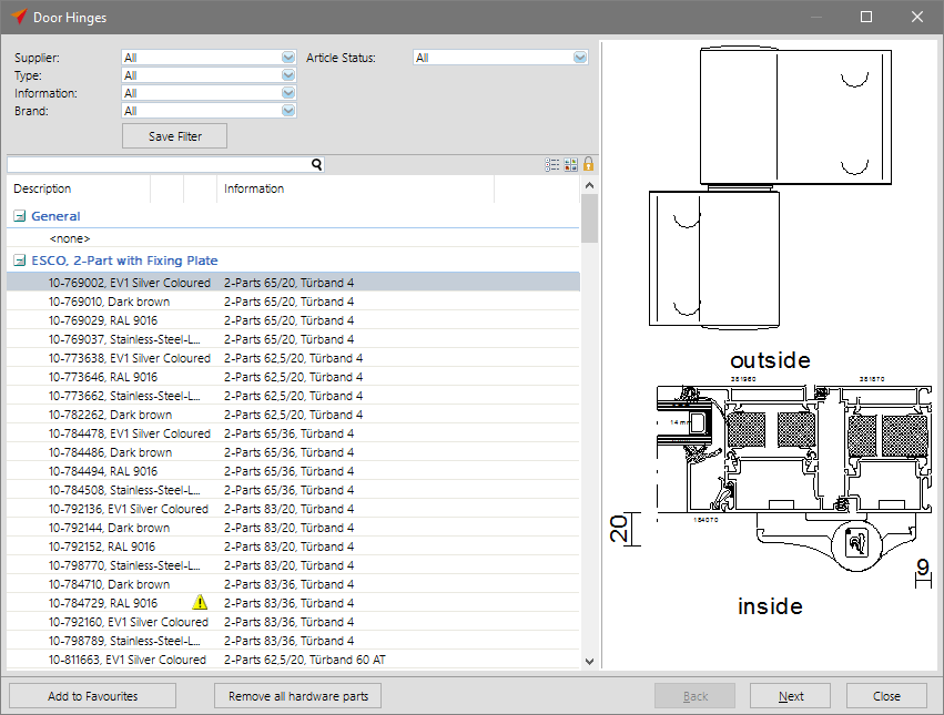
New in version 11 is the simplified positioning of the components on your element (here with the example of door hinges).
In the default setting, the position of the hinges is determined automatically.

If you prefer to arrange the hinges manually, this is now even easier with the new positioning tool.
Enable the "Manually" option and enter the desired valued in the text boxes for "Overwrite dimensions."
The changes made here are also updated in the schematic on the left side.
Below the input mask is a field that allows you to freely position the hinges.
You can use the input formulas common for entering elements (e.g. G/2; G = total height)
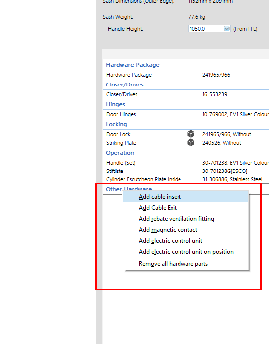
Selecting Additional Hardware
Components such as cable transitions, electrical controls etc. can be added by double-clicking on "Other Hardware."
Changing Selected Hardware
The configuration of the individual components can be easily changed by double-clicking on the item with the mouse button.
Additional Hardware / Machinings
Hardware and machinings can also be entered manually.
These function is recommended, if e.g. hardware shall not be listed in a printout.
Create a new entry by clicking on the button "Add". A new dialogue appears. Here you may select the items and set the display options for estimation and quotation.
Machinings can also be added. Click on the button Add and select the group, side and leaf.
Project Hardware Packages
If you often use the same hardware combinations you are now able to save your own hardware configurations by using the function "project hardware packages".
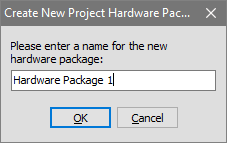
Create a position with hardware articles. Then select the button "Save as Project Hardware Package" on the left.
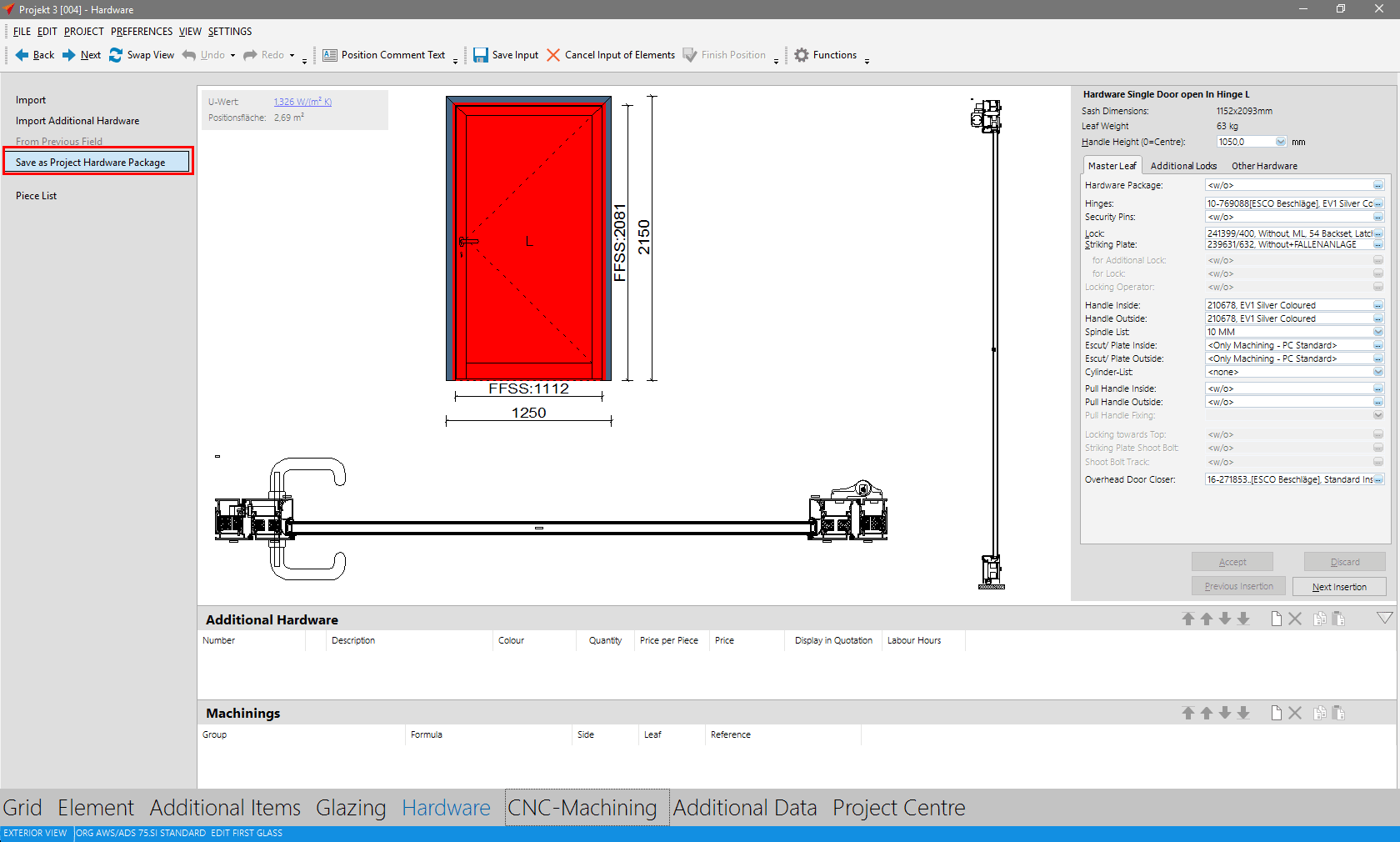
Enter a name for the new hardware package.
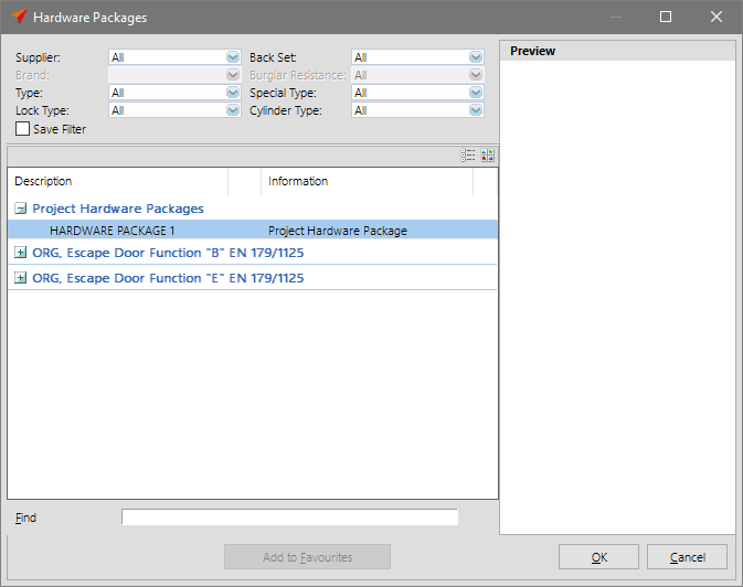
This package is now also available for other positions.
To insert a package click on "Hardware Package" in the hardware selection on the right side.
Select your hardware package from the list that includes your own hardware configurations.
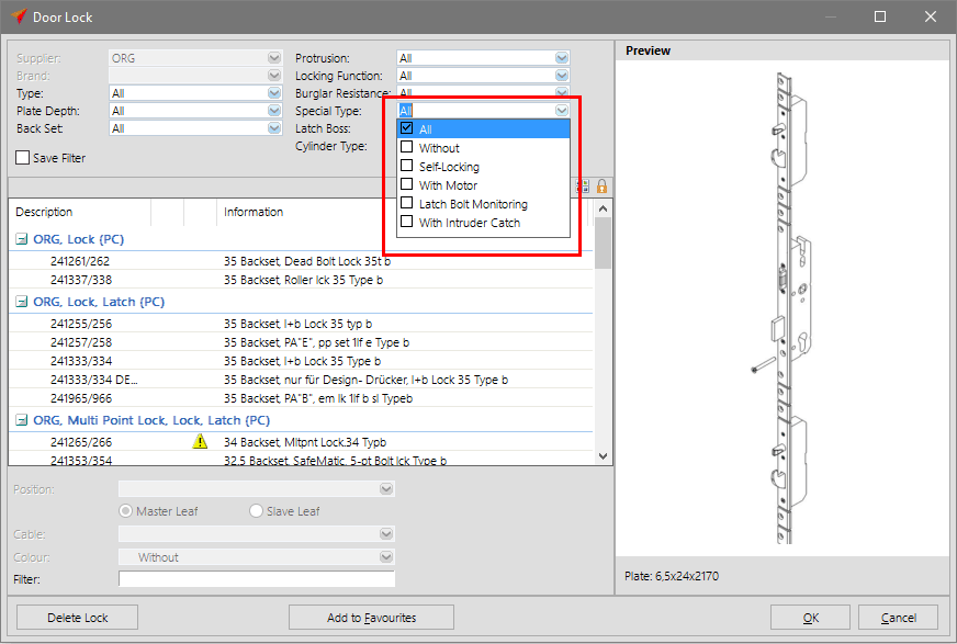
Filter Hardware Selection
With the hardware selection you can now enter several properties of the hardware under Special Type. The result with the matching items is filtered and displayed.
Chain Drives
This article explains how to create and use chain drives in the input of elements.
Note: At the moment chain drives are exclusively available for window elements.
Enter data for chain drive
As a first step enter the data for the chain drives. These can be taken from your supplier's catalogue.
Proceed as follows:
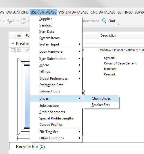
Click "User database" → "Drive" → "Chain Drive" in the project centre's file menu and select a supplier.
You get to the input mask.
Click "Add" in the toolbar to create a new item.
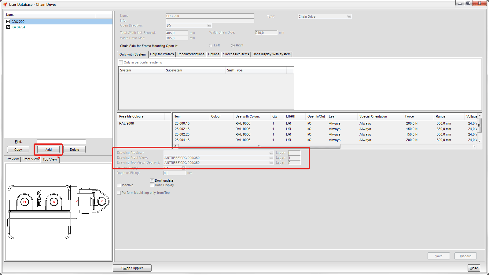
Under the different tabs you can enter the details of the item.
In the lower area you enter the drawings in different views. You can find further information below this article.
Enter data for bracket sets
As a second step enter the data for the bracket sets.
These can be taken from your supplier's catalogue.
Proceed as follows:
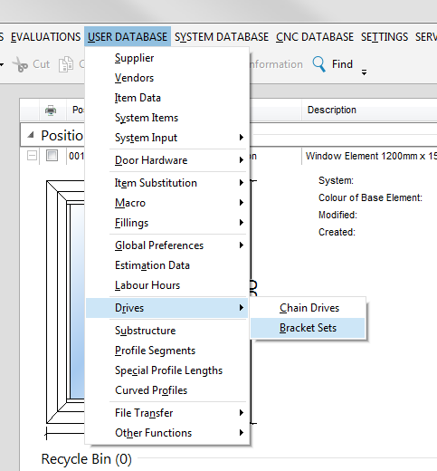
Click „User database" → „Chain drives" → „Bracket Sets" in the project centre's file menu and select a supplier.
Under the different tabs you can enter the details of the item.

In the lower area you enter the drawings in different views.
You can find further information below this article.
Create drawings
The drawings for chain drive and bracket set are created separately.
Drawings for chain drives
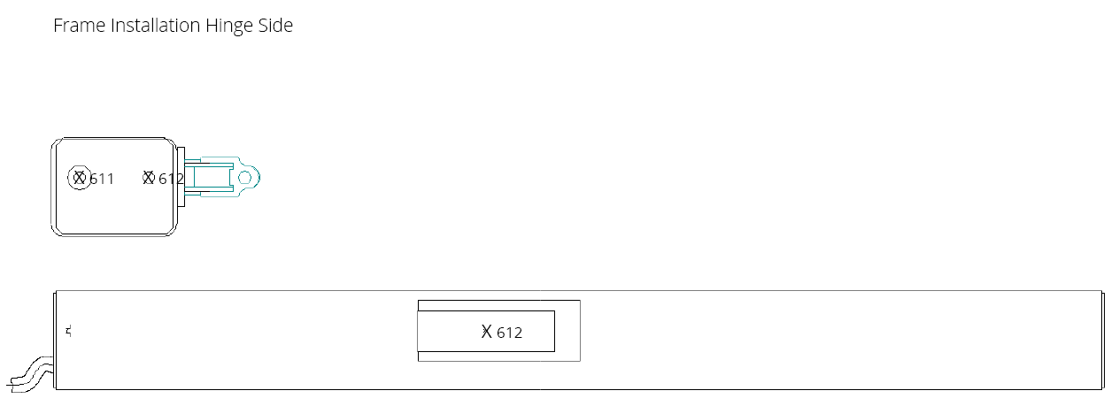
Initial setting for chain drives is always frame installation hinge side.
Drawings for brackets
Brackets are drawn in the type of mounting in which they are used.
Drives and chains are drawn flush face or with the entered „Minimal offset".
The chains and the chains at the drive are coloured in turquoise.
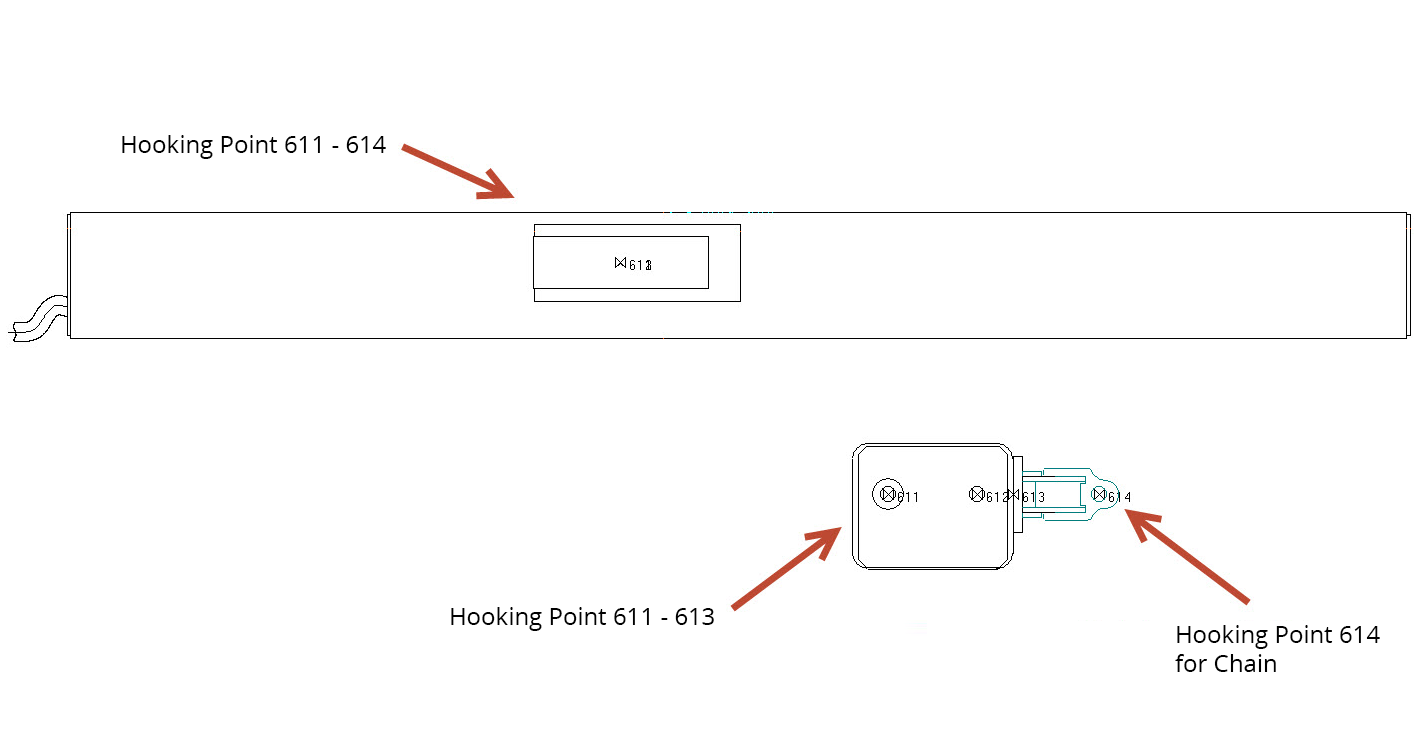
Hooking Points
The following hooking points are used:
- 990 for the bracket set depending on the type of mounting upper edge of the sash or lower edge frame.
- 611-613 for rotation point drive (up to 3 rotation points per drive possible, starting with 611)
- 614 for rotation point chain
This is the initial setting for tilt windows with frame mounting open in.
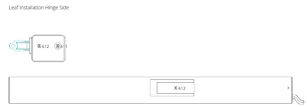
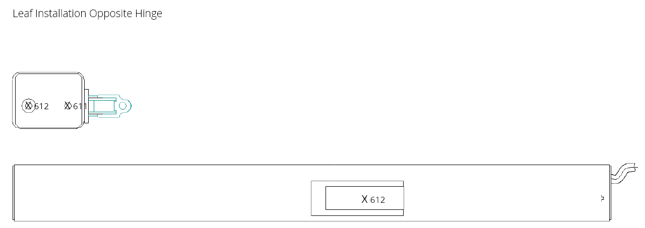
Tilt window drives are rotated and mirrored in four types of mounting.
In case of top hung windows all cuts have to be mirrored around the x-axis and all views rotated by 90°.

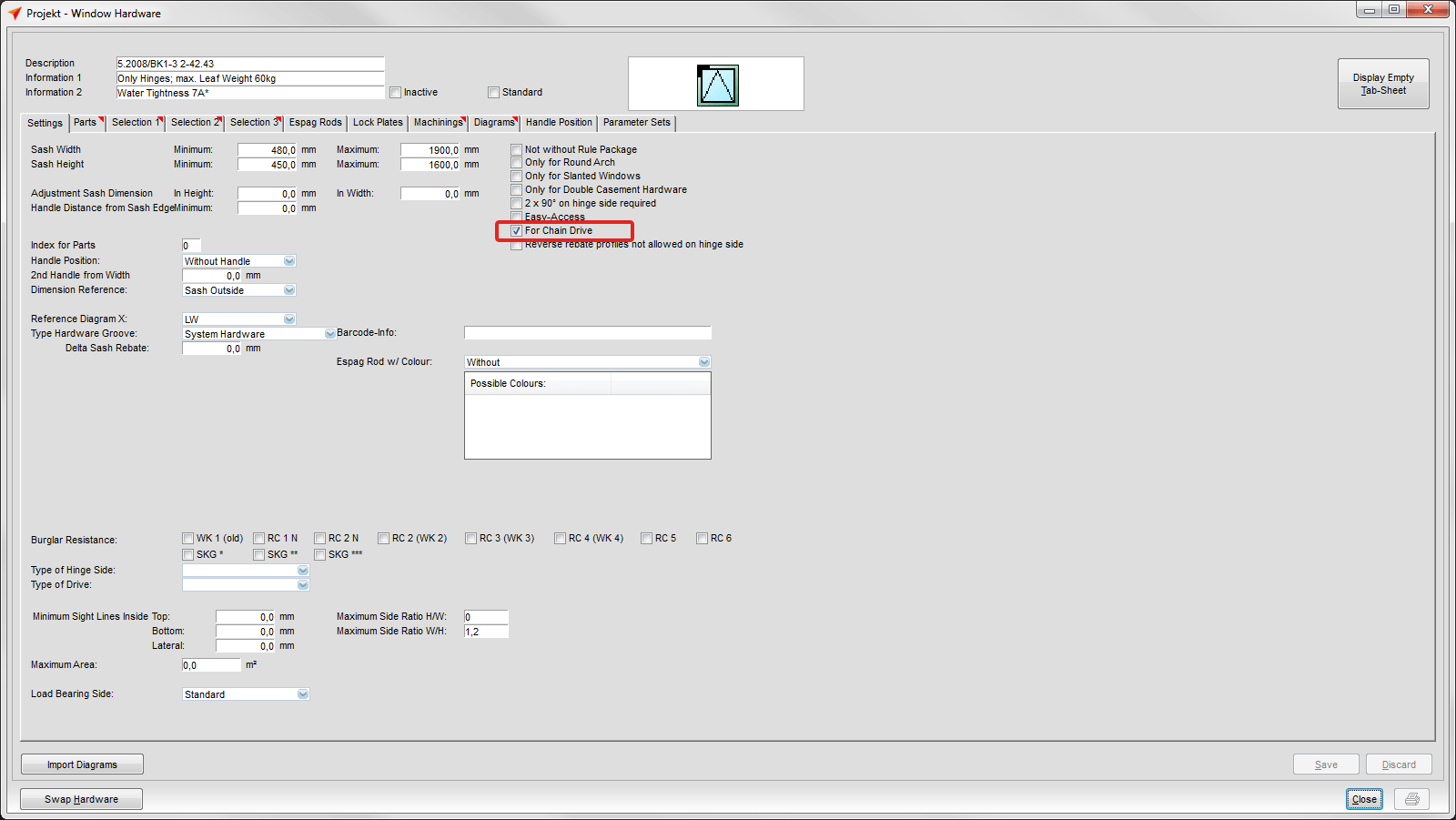
Release chain drive for window hardware
To select the chain drive in the input of elements, you have to release it for the particular hardware item.
For this purpose click „System Database" → „System Input" → „Window Hardware" in the project centre's file menu and select an item.

Activate the tab „Settings"
In the input mask you activate „For Chain Drives" under the tab „Settings" and save the settings.
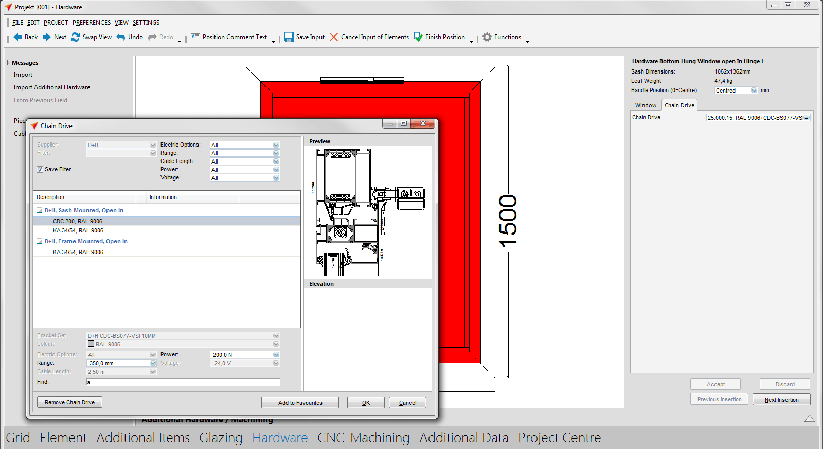
Application in the input of elements
Create a position in the input of elements and assign hardware to it.
You will find a new tab „Chain Drives" in the hardware selection.
You can select the item for the position here.


 English (UK)