Wind Load Calculation
The horizontal wind load on vertical constructions are either calculated according to different national standards or free values are applied. The following paragraphs describe exemplary how to proceed in compliance with the allowed methods of the current DIN 1055-4:2005-03. For that select under "Country" the option "Germany (DIN 1055 Part 4 and TRLV)". Other national standards follow the same input and setting principles.
Simplified Method according to DIN 1055-4
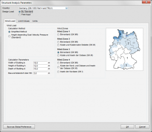
Set up "Simplified Method" under "Calculation Method". This method is generally allowed to be applied for buildings up to a height of 25 m above ground level. Besides enter the dimensions of the cuboid, i.e. building height h, building width b and building depth d, and input the altitude of the site (sea level). Finally you have to determine the wind zone and the terrain category (inland or coastal area) which match your job. In case of doubt you should always apply more disadvantageous values, i.e. "Coastal Area" instead of "Inland".
Height depending Gust Velocity Pressure according to DIN 1055-4
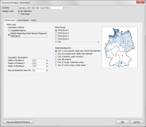
The second calculation method of DIN 1055-4:2005-03 is the calculation of the height depending gust velocity pressure. It is mainly used for buildings which exceed a height of 25 m above ground level. The wind zone is either determined directly or by selecting a city. In the last case Logikal defines the wind zone automatically. Under terrain categories there are four additional categories available apart from the two mixed profiles "Coastal Area" and "Inland". This also applies here: In case of doubt decide for the more disadvantageous terrain category. The input of the building parameters is identical to the simplified method.
Direct Input of Height depending Wind Loads
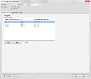
Alternatively to the calculation in compliance with DIN 1055-4:2005-03 it is possible to enter a height depending wind load directly. Select "Direct Input" instead of "Country" and click the button "Add". Please keep in mind that you must already enter the final distributed load here and not the velocity pressure which is always multiplied by an aerodynamic coefficient. Wind pressure is positive, wind suction negative. It is assumed that the load is constantly distributed over the building width and depth, i.e. different loads due to increased suction values in corner areas are not applied.
Limit Values
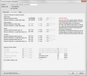
The maximum permissible values which apply to the design of beams and glasses are defined on the tab "Limit Values". For beams it is possible to determine deflection limits only, for glass panes additional stress limits can be specified, too.
Deflection Limits
Deflections of beams and glass panes are not regulated by DIN standards, general technical approvals or application guide lines. Mostly, the so called "Ultimate State of Serviceability" is defined by the demands of the glass suppliers. It is up to the user to request these values from the glass manufacturer and to enter them afterwards. Frequently applied values are "8 mm" or "L/300". Apart from the glass it is also possible to restrict the deflection of the beam spans separately for mullions and transoms. The most commonly used limit values are already suggested. If applicable they may be modified individually at any time.
Stress Limits
The maximum permissible stress values of different glass types are specified in the lower part of the form. The values which are specified in the Technical Regulations for the Use of Glazing with Linear Supports (German abbreviation: TRLV) are displayed automatically. Only the values for glass panes made of semi-tempered glass (STG) are editable, because they are regulated by general technical approvals. Common maximum permissible stress values of STG are already suggested.
Units
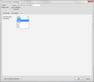
It is up to the user to determine the units of wind pressure and stress displayed in the program and on printouts. Apart from [kN/m²] or [N/mm²] alternative units like [N/m²], [Pa], [kPa] and [MPa] are available.


 English (UK)