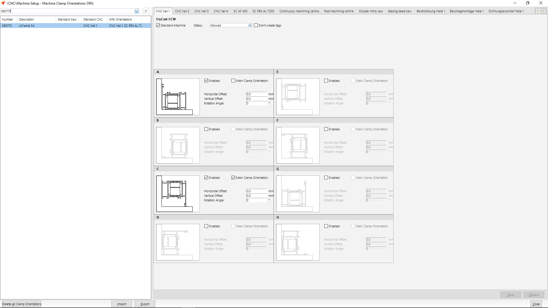
To be able to handle a profile, the position of the profile on the machine must be defined. The clamp orientation defines how the specific profile has to be fixed on the machine.
Define clamp orientations
The clamp orientations can be found at „CNC Database" > „Clamp Orientations".
The clamp orientations editor opens.
In the upper area you can see by the use of tabs, which saws and machines are installed on your system.
Note: Clamp orientations for saws only need to be set or changed manually if the activated standard orientation does not fit your working method. You can view the default orientation in the saw settings at "Profile Orientation".
Choose the saw / machine for which you would like to set the clamp orientations.
Select the profile from the list on the left side.
On the right side you see the schematic view of the profile and the eight possible clamp orientations.
The profiles are displayed from A to D each with a 90° rotation.
The clamp orientations E to H are mirrored accordingly.
Inactive clamp orientations are displayed in grey.
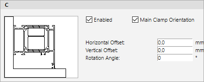
Activate the " Enabled" option to activate a clamp orientation.
If you want the orientation to be the main clamp orientation, activate the "Main clamp orientation" option.
In addition to a horizontal and a vertical movement, you can also define a free rotation angle here.
For saws and CNC machines with cutting, a maximum of two clamp orientations per profile can be released.
On CNC machines the selection of the clamp orientations depends on the main clamp orientation.
If you have set up the main clamp orientation in the area A to D, we recommend that you also remain in the non-mirrored area for the other clamp orientations.
If you nevertheless select clamp orientation from the range E to H and the main clamp orientation is in the range A to D, you must always rotate the profiles 180° around the longitudinal axis.


 Deutsch
 English (UK)
 English (US)
 Español
 Français
 Italiano
 Nederlands
 Polski
 Türkçe
 Čeština
 Ελληνικά