Para crear sus propias conexiones de pared, por favor vaya a "Datos Usuario" -> "Introducción Sistema" -> "Conexiones pared" primero.

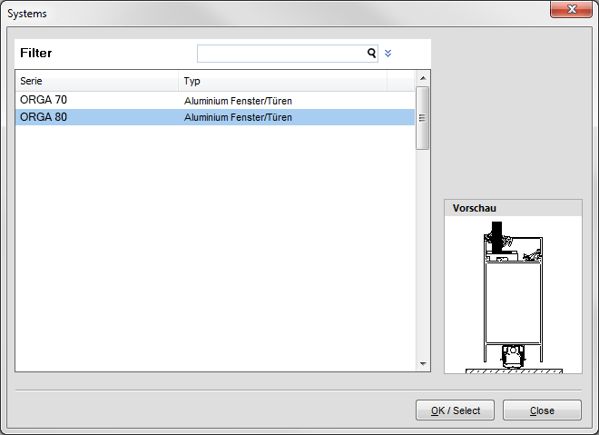
Para comenzar, seleccione el sistema del perfil que quiere utilizar para la conexión de pared.
Haga click en "Añadir" en la barra de herramientas y aparecerá un formulario en blanco a la derecha.
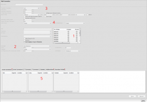
Introduzca un nombre para la conexión de pared bajo "Descripción. Los siguientes puntos nter a name for the wall connection under "Description". The following points refer to a wall connection created exclusively with drawings of already entered economic items:
Reference point 1: Here you enter all profiles to which the wall connection is applied.
Reference point 2: Under "View" you can create a dimension. Once the wall connection is selected in the input of elements, the programme will show you a dotted line with the entered dimension, based on the edge of the "Element". This enables you to see on which side the wall connection was used, when looking at the view in the input of elements. When using several wall connections, different sight line dimensions should be used for a better differentiation.
Reference point 3: With "Possible Orientation" the positioning of wall connections can be specified e.g. for window sill connections.
Reference point 4: In case you access a machining centre you can assign the work groups here.
Reference point 5: Under the tab "Additional Items/Sealings and Additional Profiles" items from the economic data can be assigned to the wall connection. These can be found again later on in the piece list. In case a drawing is assigned to the economic item, you can position the drawing via the insertion points (point 5). When entering a new item (e.g. under additional profiles) please use even values for the sake of simplicity e.g. x:10, y:10. To calculate the coordinates for the positioning, save the wall connection. Once saved, you will see the profiles displayed in the preview left down below.
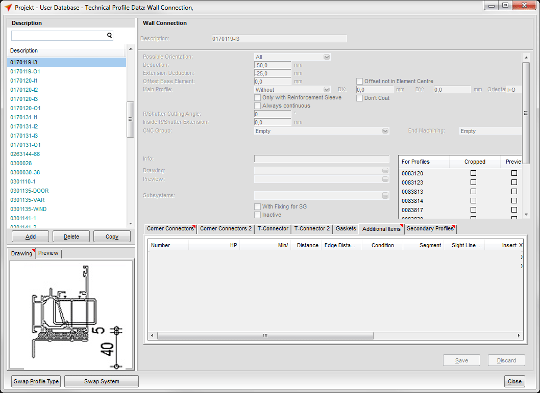
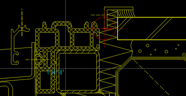
Click the preview with the right mouse button and select the option «Display in CAD» from the short-cut menu. You get to the CAD. With the F2 key you catch the point. With F9 you set the coordinates x and y to «0». After this, catch your reference point with F2 and note the position of values x and y.
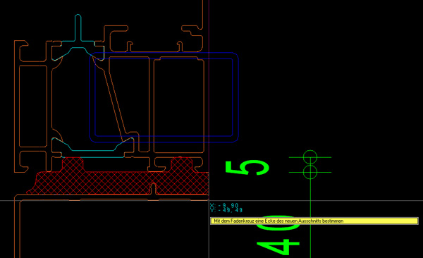
Offset both calculated points against the already saved values and save the modification.
Should the preview be incorrect, repeat the previous step and correct the positioning of x and y. The wall connection can now be assigned to the position in the input of elements and will be displayed in the cross section accordingly.
Positioning of a DXF/DWG Drawing
For the positioning of a DXF-/DWG drawing you got to have the CAD-Suite 2D. First load the drawing into CAD and save it under system drawings of your respective profile supplier in the file «Wall Connections»:

Afterwards load a drawing – in this case a frame profile – and position it within the drawing:
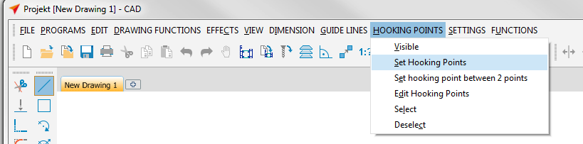
Select the option «Set Hooking Point» under «Hooking» and select the hooking point «990» in the CAD's file menu:
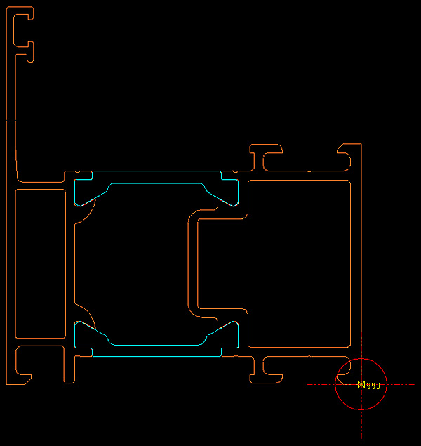
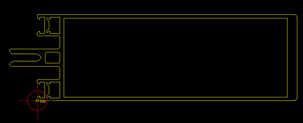
The position of hooking point «990» is set by default and displayed in the following three pictures:

After setting the hooking point «990», remove the loaded profile from the drawing and save the drawing in the picture file „Wall connections":
Afterwards the drawing path has to be entered under «User Database» → «System Input» → «Wall Connections»:

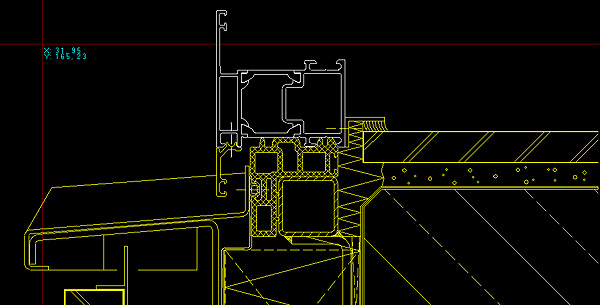
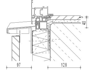
Save the data by clicking «Save» in the toolbar. In the preview and in the cross section the wall connection will be as follows:


 Español