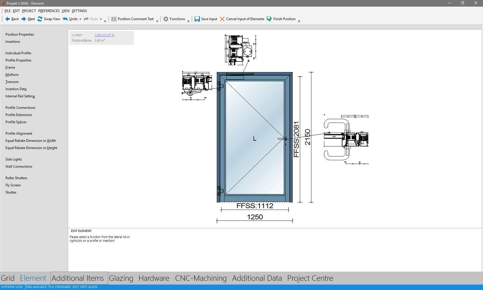
In the insertion input you determine the insertions of a position.
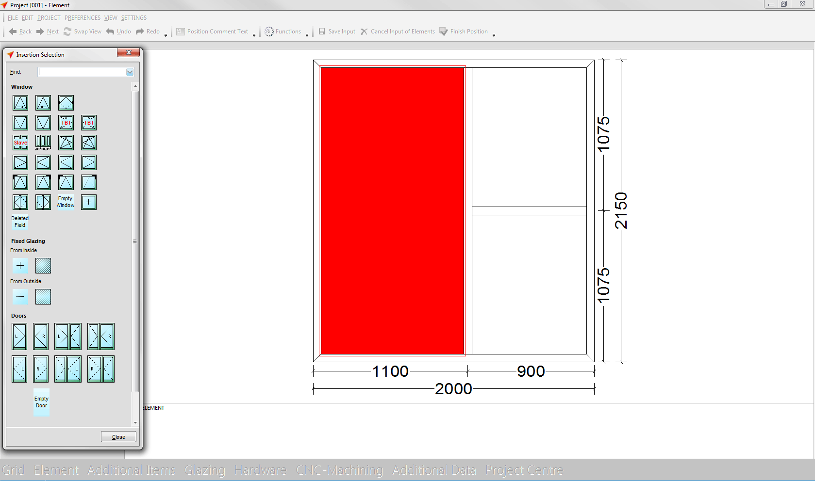
On the left all available insertion types for windows and doors are displayed.
The insertions are determined one after the other.
You may also select the different fields by clicking on the fields.
More insertion types are listed in the "Find" drop down menu.
After you have entered the insertions, the "Position Properties" are automatically displayed. Alternatively you can select the "Position Properties" button on the left.
Here you can determine glazing bead and gasket variant. You can also select drainage, corner connection and colour options.

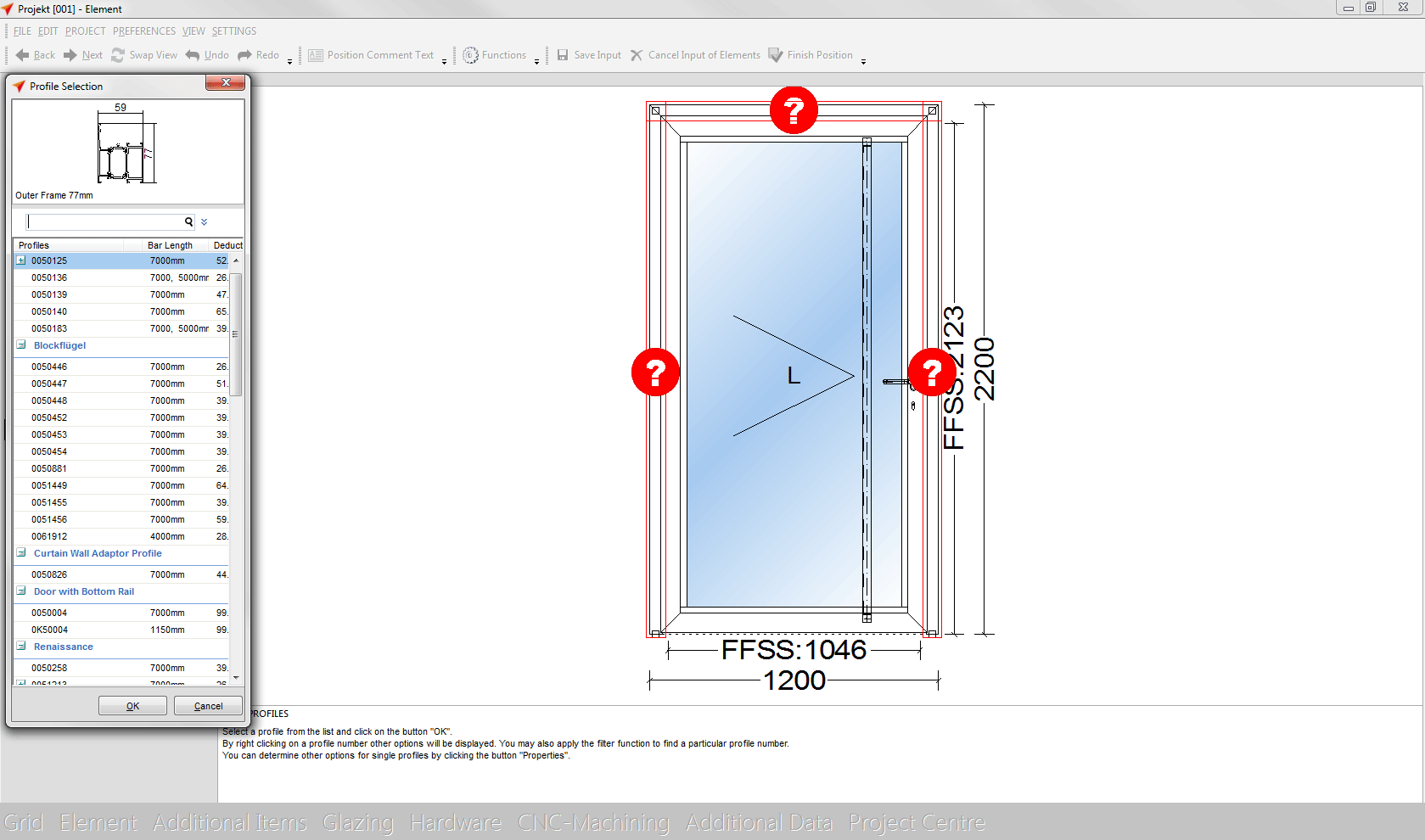
After this you need to define the profiles of the position.
You select the different profiles from the list on the left. The active element is highlighted with a question mark.
If you right-click on an item the following context menu appears:
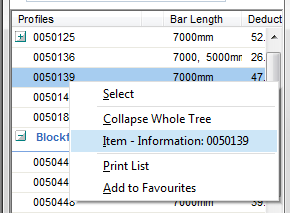
Frequently used items can set as a favourites by selecting the "Add to Favourites" option.
Favourites are always displayed at the top of the list so that they are quickly accessible.
Click on "Item – Information" to get detailed information about a selected item.

Insertions
By clicking on the "Insertions" option you can modify the existing insertions in the position. You can access the insertion input and select the new insertions.
Individual Profile
You may determine individual profiles of a position. Select a single profile or multiple profiles and click on the "Apply" button to change the items.
Frame
Click on the "Frame" button to assign a new frame to the position.
Mullion
Select the "Mullion" button to insert mullions into the position.
Transom
Click on the "Transom" button to determine new transoms to the position.
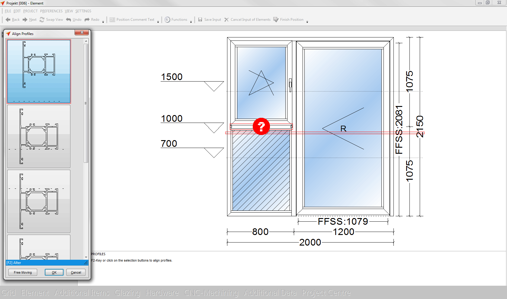
Profile Alignment
The "Profile Alignment" function enables you to move profiles in an element.
There are two ways to align profiles, as listed below.
For instance you can set horizontal guide lines.
Click on the "Guide Lines" button and add a new one.
Then select the profile(s) you want to align at the guide line and click on "Apply".
![]()
On the left hand side you will see all alignment possibilities that are available for this profile.
The second possibility is a free offset of the selected profile.
First click on Profile Alignment, then select the profiles.
Click on the "Free Moving" button.
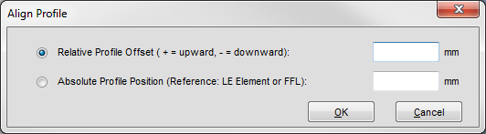
Here you are able to select between the "Relative Profile Offset" and "Absolute Profile Position" options.
Enter a value and click "OK" in order to apply the changes.
Profile Connections
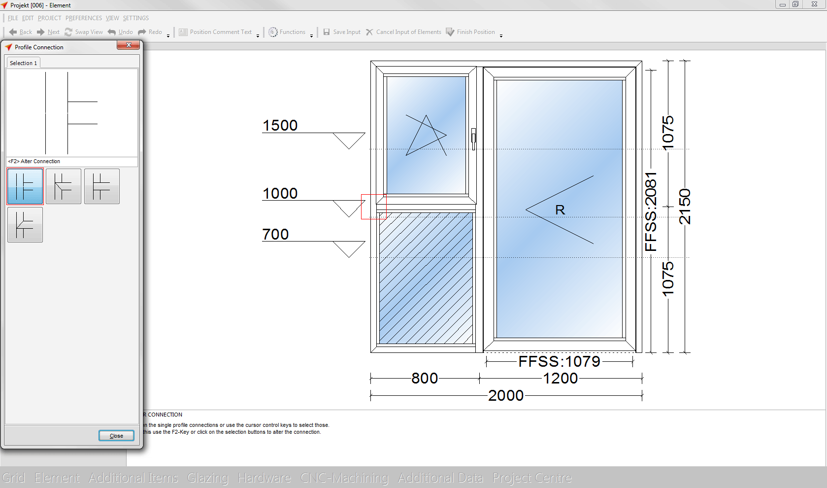
Profile connections can be modified by clicking on the "Profile Connections" button. Select the connections by clicking on the profile connection on your element. On the left you will see an overview of all possible variations.
Profile Extensions
To determine the extensions of a position click on the "Profile Extensions" button.
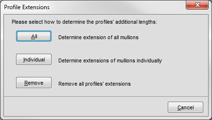
Select the "All" option to modify the top and bottom extension. These specifications will be applied to all mullions in the position.
If you click on the "Individual" option you can then select single and multiple mullions by clicking on the mullions you want to extend.
Profile Splices
Click on the "Profile Splices" button to determine where you want a profile splice to be positioned.
The following window appears:
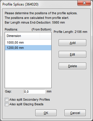
Select the "Add" button (or Insert-Key on your keyboard) to define the dimensions of the profile splice. Please note that the end-deduction depends on the bar length.
The end-deduction of a profile can be modified in the additional opitimisation.
Secondary Profiles and Glazing Beads can also be considered by ticking the "Also split Secondary Profiles" or "Also split Glazing Beads" checkboxes.
Profile Reset
Click on the "Profile Reset" button to determine new profiles for the position.
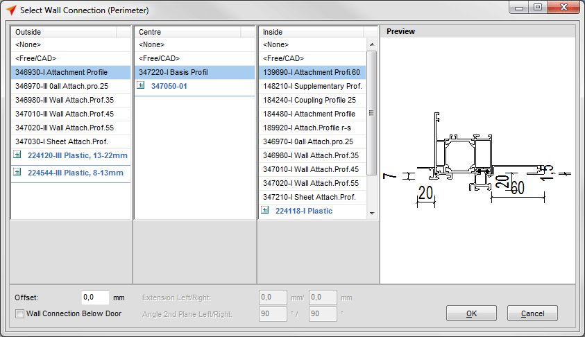
Wall Connections
Use this function to create wall connections.
You are able to determine all items and specifications needed for the wall connection.
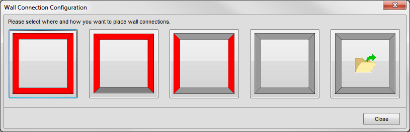
If you want to enter an offset please enter a value in the "Offset" field in the bottom left corner.
Wall Sections
You can enter specific settings for wall sections. On the right the preview of the wall section is displayed.
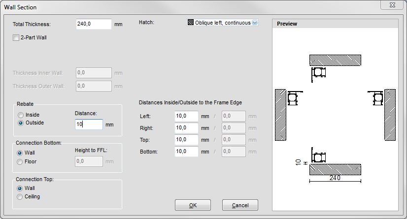
Enter the total thickness and determine a hatch.
2-part walls can also be entered by selecting the "2-Part-Wall" option and defining the thickness of the inner and outer wall.
You can also specify the inside and outside distance of the element edge.
Fly Screen
Click on the "Fly Screen" button to integrate fly screens into a position.
A new window with different templates appears:
Select a template and the "Fly Screen" specification window opens:
You can enter your own fly screens in the position library.
Internal Rails
Internal Rails can be entered into a position by selecting the "Internal Rail Setting" button.
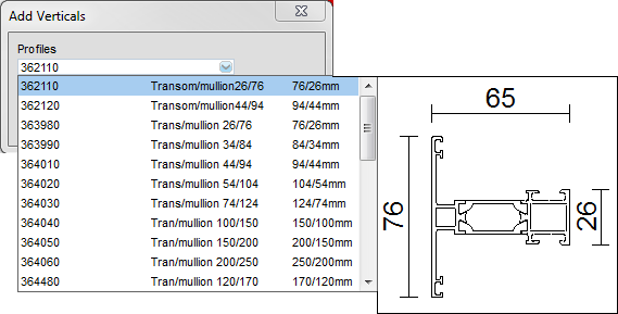
A new window appears. Here you can add verticals and horizontals rails to partial fields.
Determine the number of verticals / horizontals rails.
Determine the adjustment by selecting the "Equal Glass Dimensions" or "Enter Free Dimension" option.
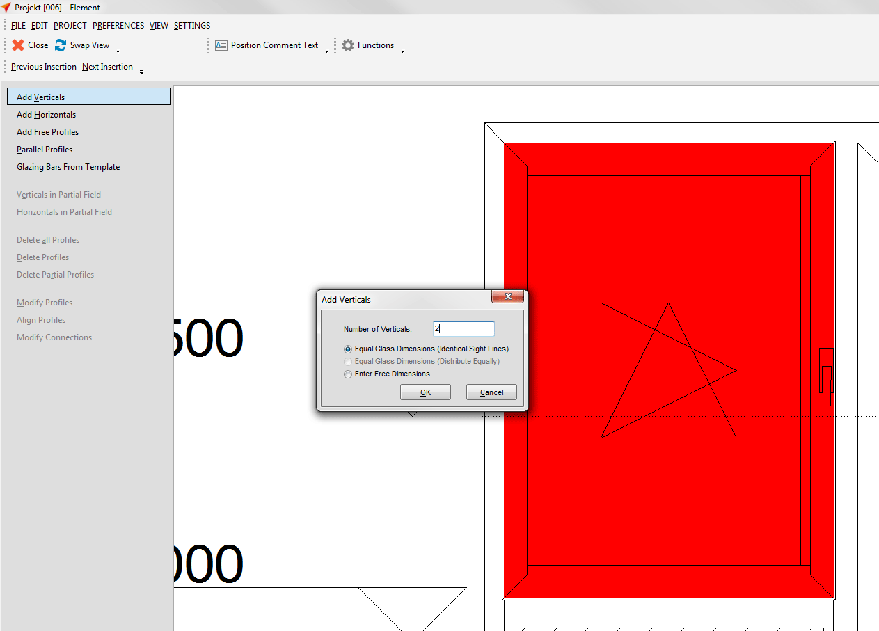
Use the "Equal Glass Dimensions" option to make the glass panes equal in the position.
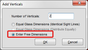
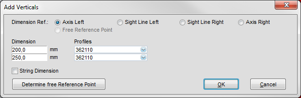
By using the "Enter Free Dimension" option you determine the position of the rails yourself.
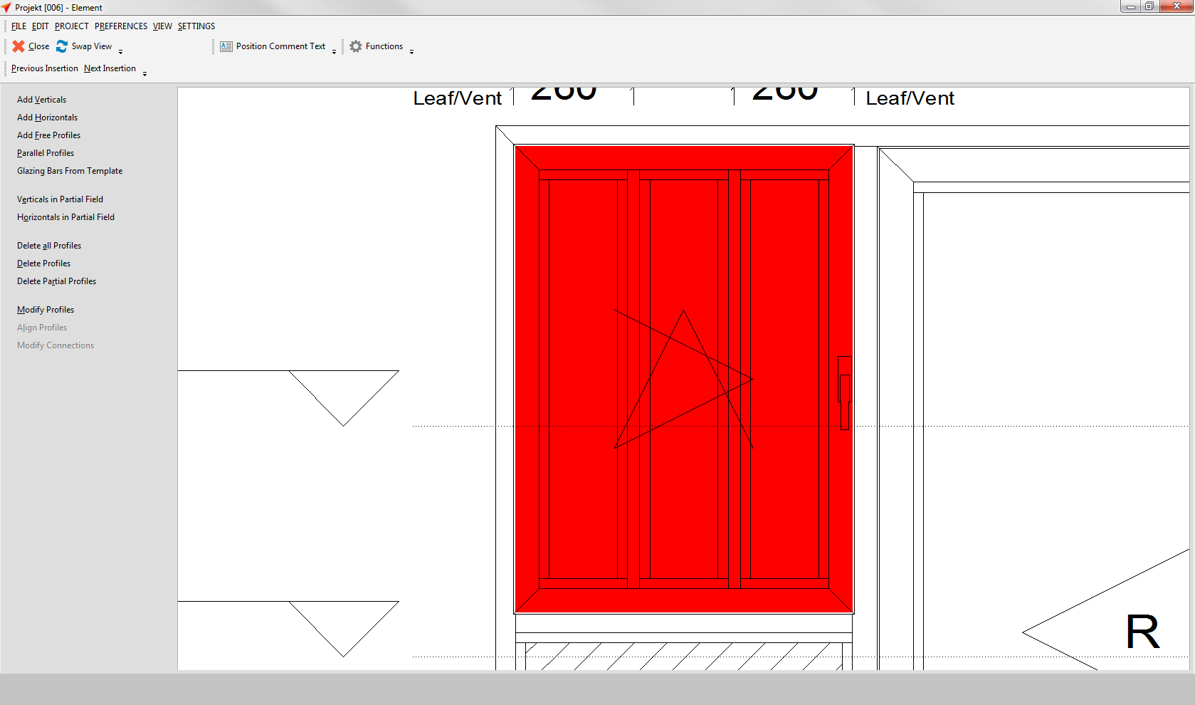
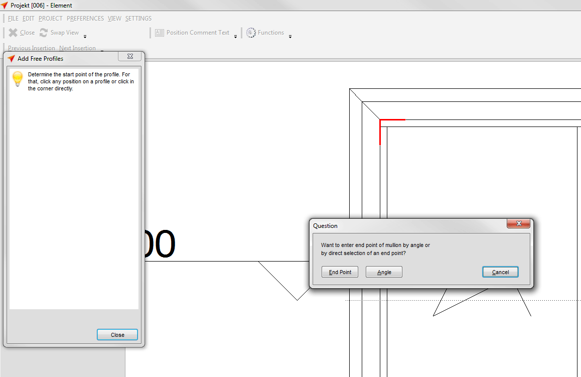
Add Free Profiles
Click on this button to enter free profiles. Determine the start and endpoint by clicking where you want the profile to start and end. You may also enter the angle of the rail.
Delete Profiles
There are several functions to delete profiles. Depending on which profile you want to delete, select "Delete all Profiles", "Delete Profiles" or "Delete Partial Profiles".
Modify Profiles
To change a profile item, click on the "Modify Profiles" button.
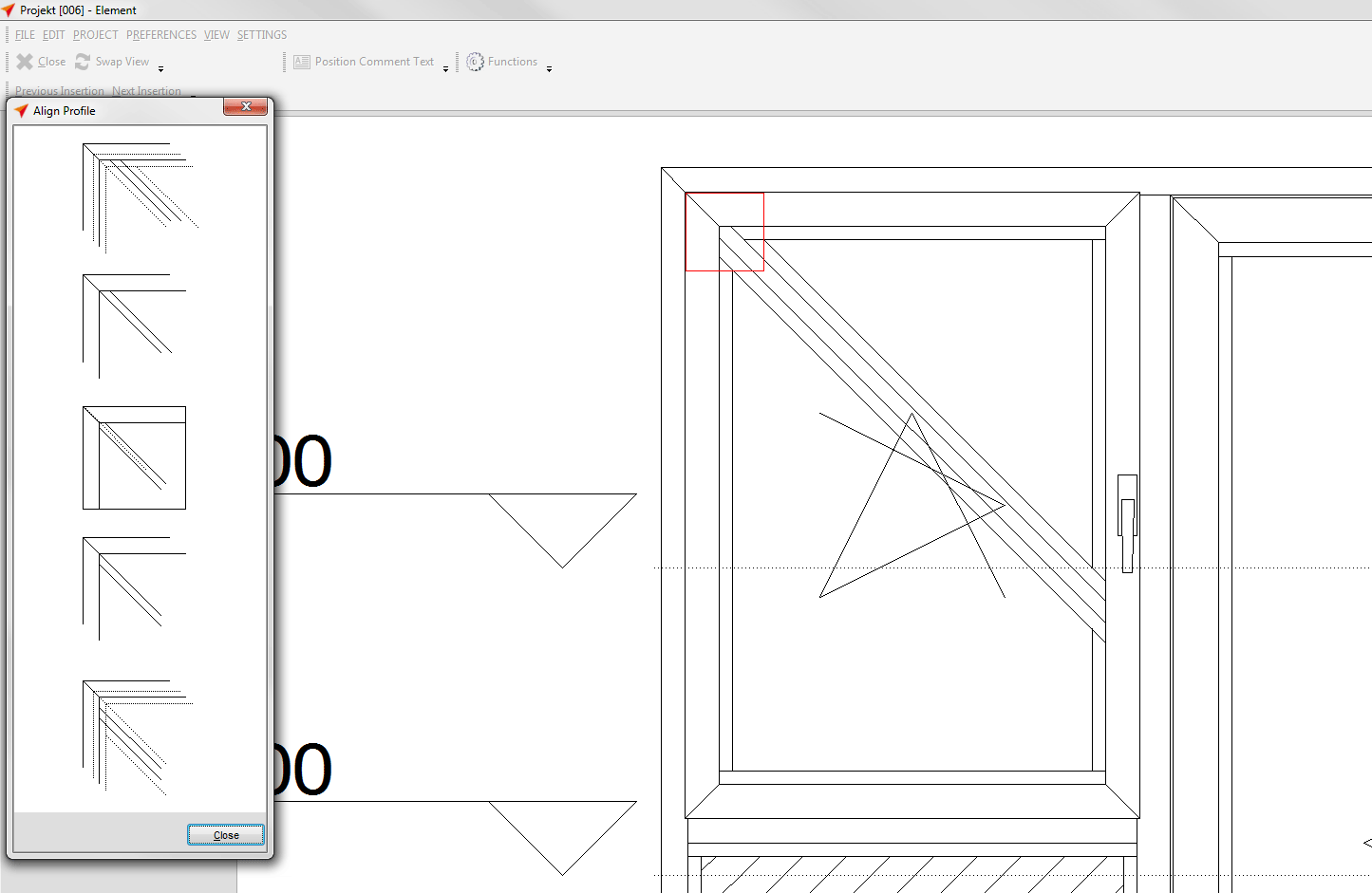
Align Profiles
If you have entered a diagonal profile, you can align these by using this option.
Click on the start or end point and select the connection possibility on the left.
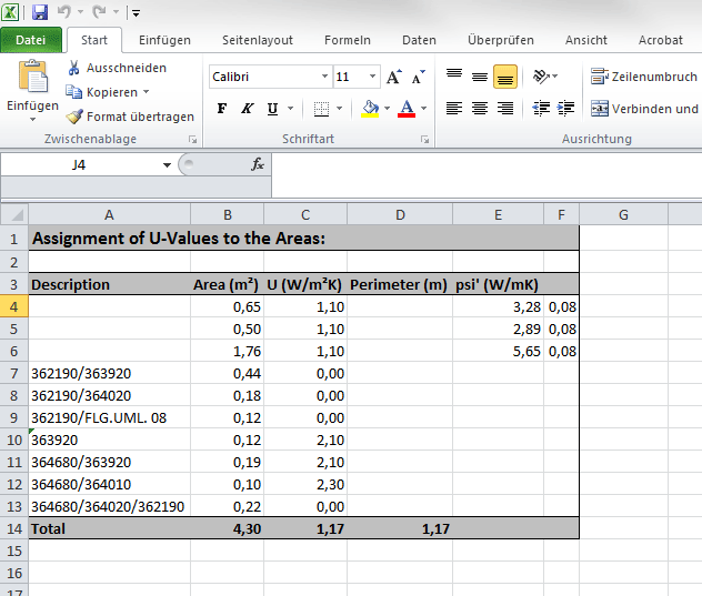
U-Value
This option allows you to display the u-values of the used profiles.
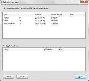
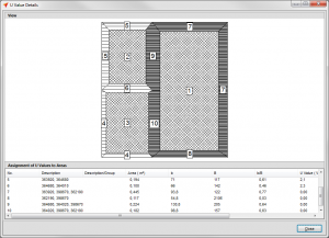
Click on the "Details" button to get more information about the u-values of every profile.
You can also open this infomation in Excel by selecting the "Excel" button.
Dynamic Display of Opening Angle
The opening angle can now be dynamically displayed in the cross section.
Actual glass size must be activated and door hinges have to be assigned.
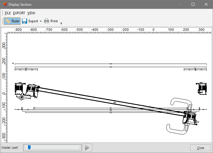
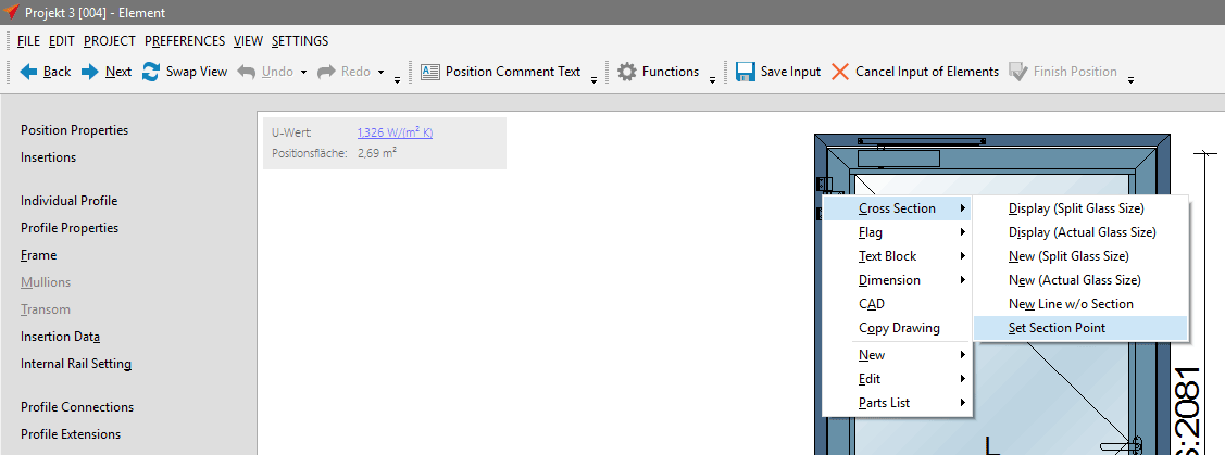
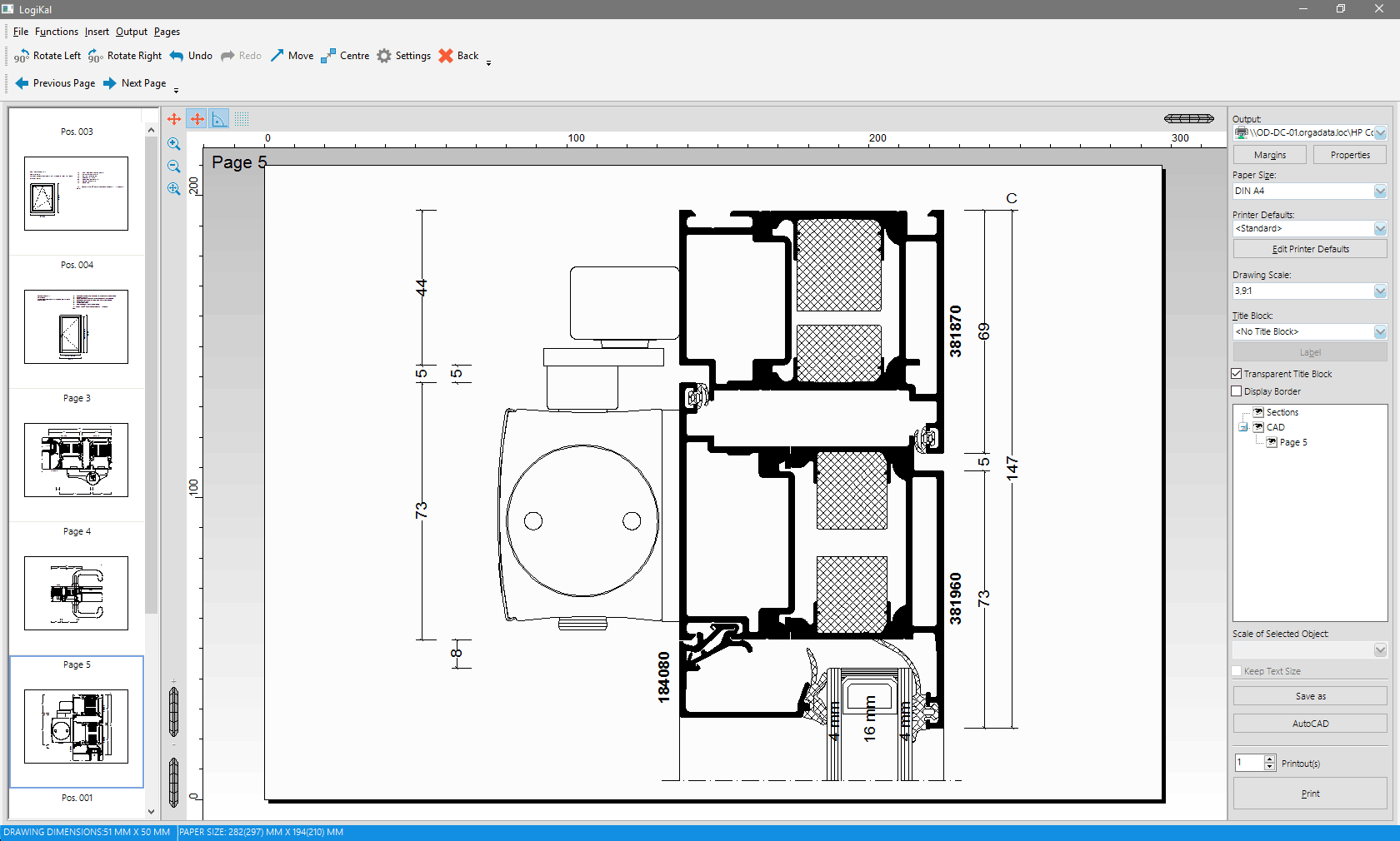
Catalogue function using section point
Now you can also display individual cross sections in the printouts.
Right click on the point of the position that you want to display as individual cross sections. Select in the context menu Cross Section -> Set Section Point.
Give the designation for a text, determine on which printout the section should be displayed, determine the type of marking and the size.
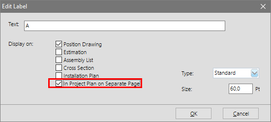
Activate the option In Project Plan on Separate Page to printout the section area on separate pages.


 English (UK)