CNC machining
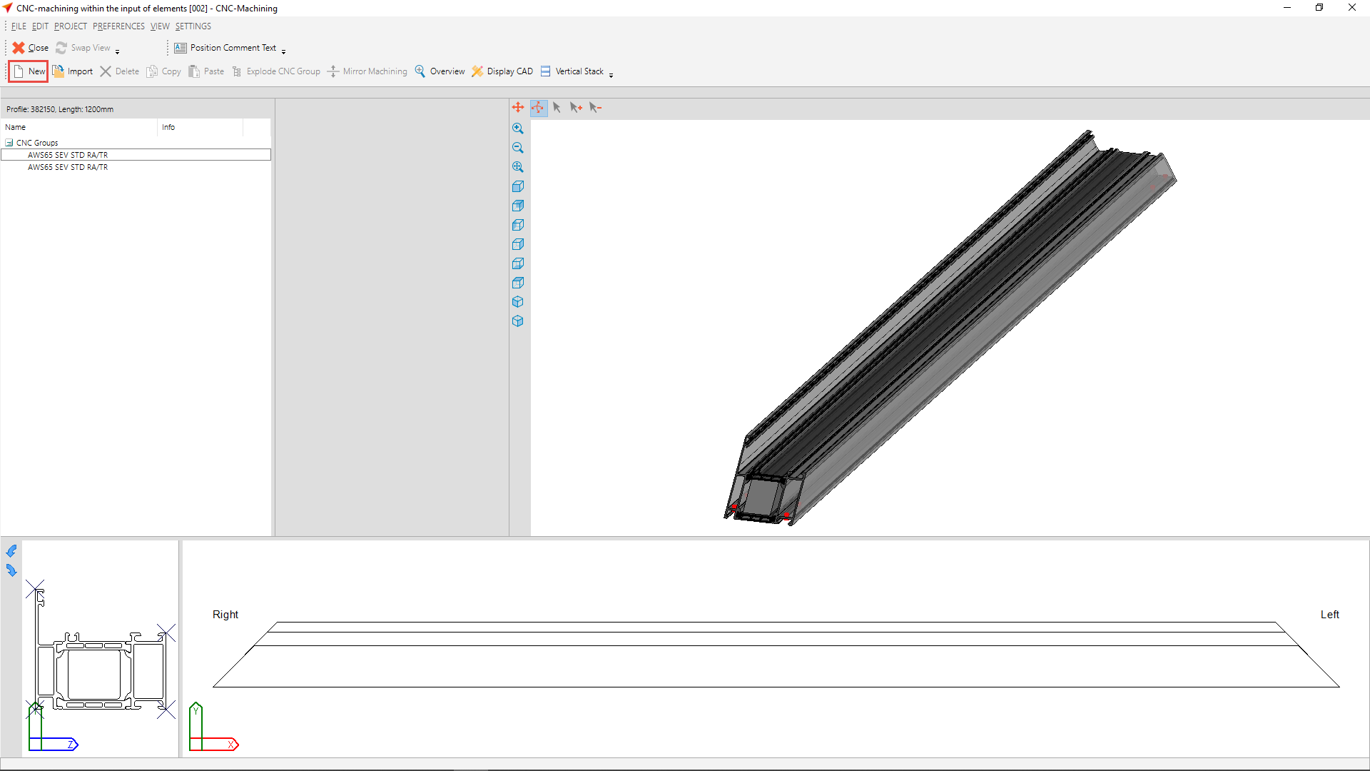
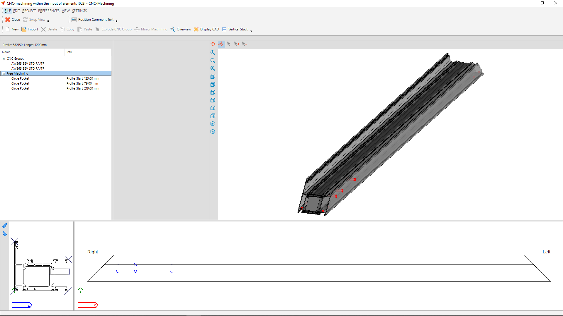
For the CNC machining in the input of elements you will find the position sketch in the right area. Click with the cursor on a profile in the position sketch to display the associated bar drawing with the machinings in the lower area.
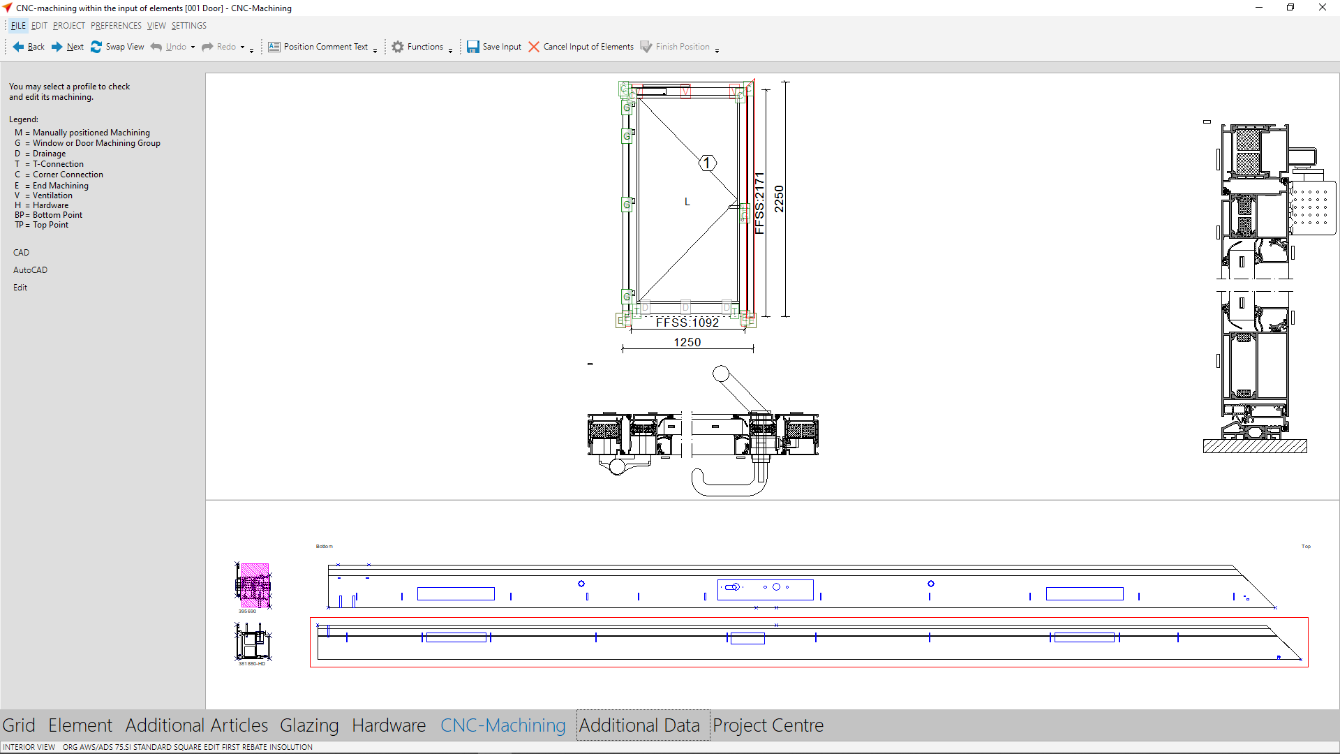
On the left side you will find a table with the abbreviations of the machinings, which are used in the position drawing on the right side.
| M | Manually positioned machining |
| G | Window or door machining group |
| D | Drainage |
| T | T-connection |
| C | Corner connection |
| E | End machining |
| V | Ventilation |
| H | Hardware |
| BP | Bottom point |
| TP | Top point |
Directly below, you will find the "CAD" button. Use this button to display the bar drawings of the currently selected profile in the internal CAD. If you have an interface to AutoCAD, you can also display the bar drawings in AutoCAD.
You can view the machinings in a detailed 3D view. To do this, double-click on a profile and the detailed view opens.
Alternatively, you can click on "Edit" on the left side to display the machinings on the currently selected profile.
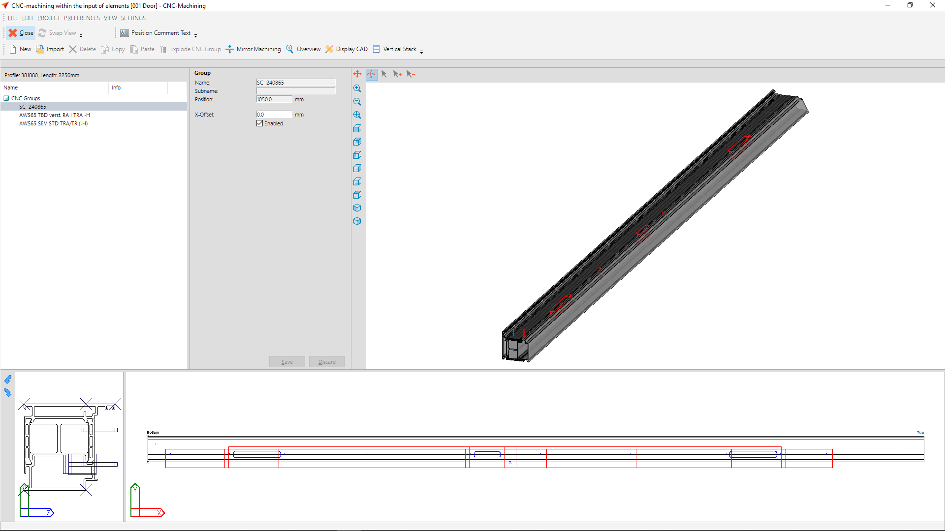
On the right side you will find a 3D view of the profile including the machinings. You can have a look at the profile from different angles. To do so, move the cursor on the profile and rotate it with the left mouse button pressed down. Alternatively, you can also use the blue symbols located on the left of the 3D window.
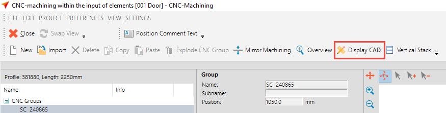
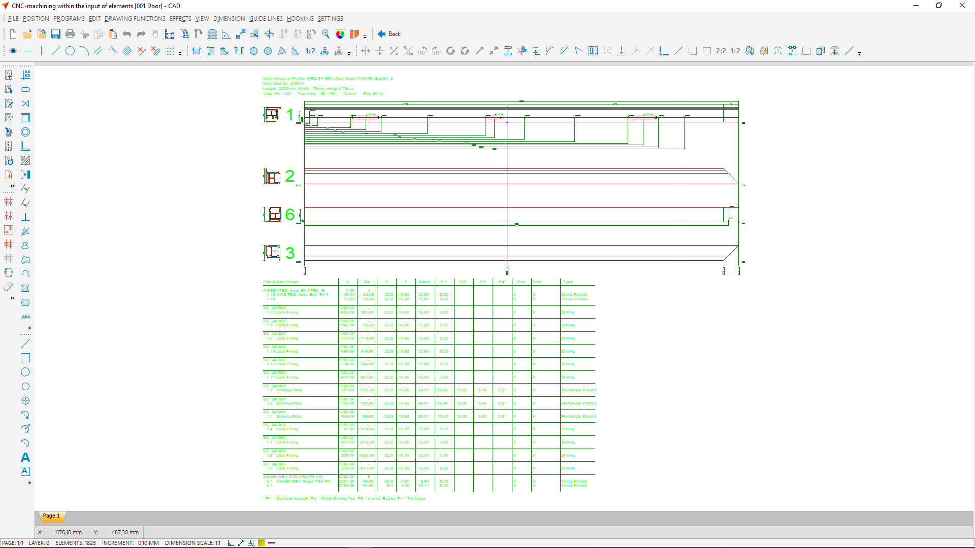
For detailed bar drawings of the selected profile with all machining faces, click the "Display CAD" button.
Click on the "Overview" button to display a comparison of the profiles with the machinings relating to them, e.g. frame with strike plate + leaf with lock.
Free machining groups
Machinings can be individually programmed on a bar in CNC-Machining.
Switch to the detail view.
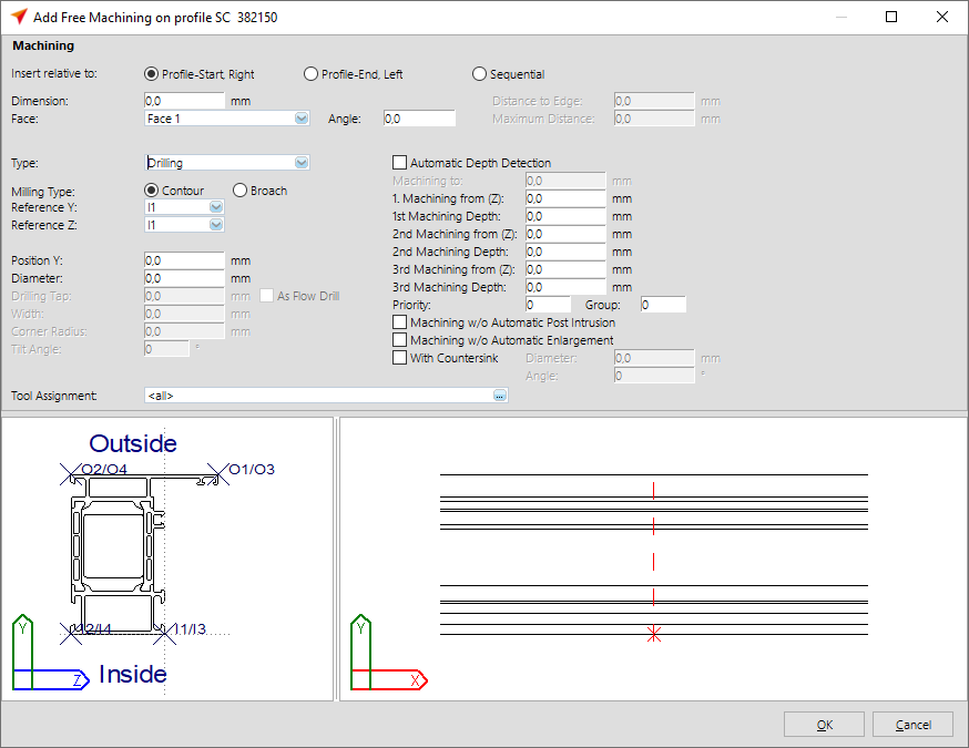
Click on "New" to create a new free machining.
The input window for the machinings opens.
Creating machinings in the input of elements is similar to the CNC database. For more information, please refer to the chapter "Enter Machinings".
If you have already created free machinings in the CNC database, you can import them into CNC machining.
Click the "Import" button.

In the following window, select the free machinings and groups in the upper area.
Note: The groups are always displayed at the top with bold font, whereas the machinings are listed below with normal font.
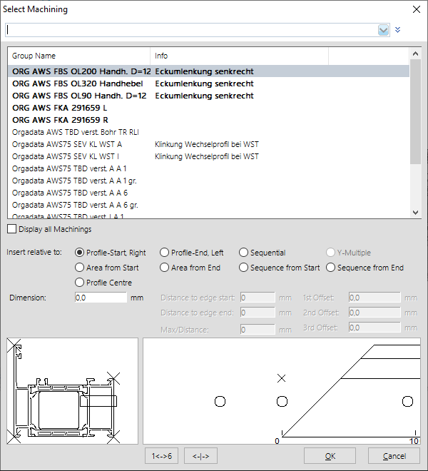
Directly below, under "Insert relative to", you determine how the machinings and groups are aligned.
For the options, here "Profile start, right", "Profile end, left" and "Profile centre", you also enter a value under "Dimension".
For the options "Sequential", "Area from Start" and "Area from End" you enter the edge distance, the length and the maximum distance of the machining placements. Please note how the profile is determined (regarding left and right side) and whether the position is selected correctly. If required, you can also enter a minus value here.
With the options "Sequence from Start" and "Sequence from End" the edge distance and the distance of the machinings are entered.
In the lower area of the import mask you will find two more buttons.
![]()
With the button "1<->6" you can move the machining on another profile face.
The button labeled "<-|->" is used to mirror the machinings on the profile.
 |
 |
A new free group is generated from the individual machinings. This is displayed in the list on the left at "Free groups".
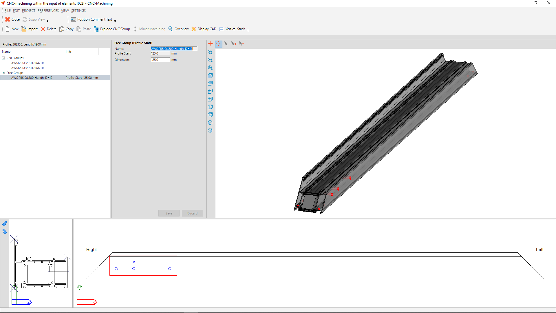
On the right oft he machining list you can change other group data.
To display free groups as individual machinings, right-click on the free group and select the "Explode CNC Group" option.
Note: Unlike free groups, system groups cannot be exploded.

The individual free groups are now displayed in the list.
Note: If a group consists of several areas (several machinings within a group), subgroups are displayed at this point.
If you explode a free group again, the free machinings that are contained in the group are displayed.
Further display- and output – functions
In the area of the bar drawings below, the context menu (accessible by clicking the right mouse button) provides additional functions for the output of the drawing.
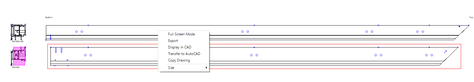
Click on "Full Screen Mode" to display the bar drawings full screen.
If you want to save the drawing in a common format (e.g. dxf, dwg, jpg etc.), click on "Export".
To open the bar drawing in CAD, click on "Display in CAD".
Click "Transfer to AutoCAD" if you want to open the drawing in AutoCAD.
Further display functions are available in the file menu under "View" > "CNC Machining".
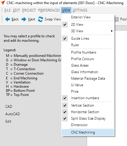
Both functions are activated by default.
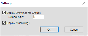
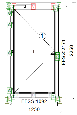
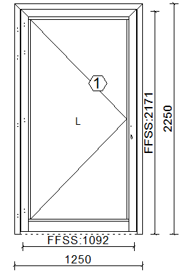
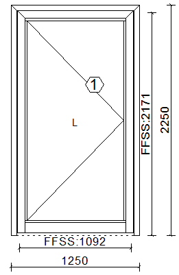
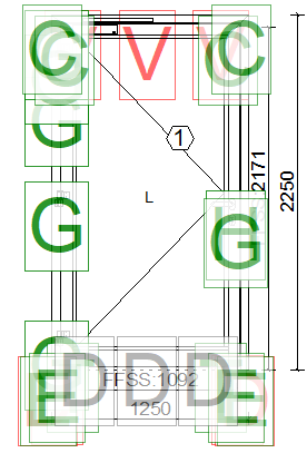
These view settings have the following effect on the position drawing:
| Display drawings for groups | Do not display drawings for groups | Display machinings activated | Display machinings deactivated | Symbol size e.g. 25 |
|---|---|---|---|---|
 |
 |
 |
 |
 |


 English (UK)