Installation
Upon delivery of the program, you receive a USB dongle and an USB-Installation card.
To install the program on your PC, proceed as follows:
- Connect the USB dongle to an USB port
- Connect the USB-Card to an USB port
Run the installation program on the USB Card.
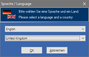
Enter your local language on the first screen.
The welcome screen appears.
Before starting the installation, please close all other programs.
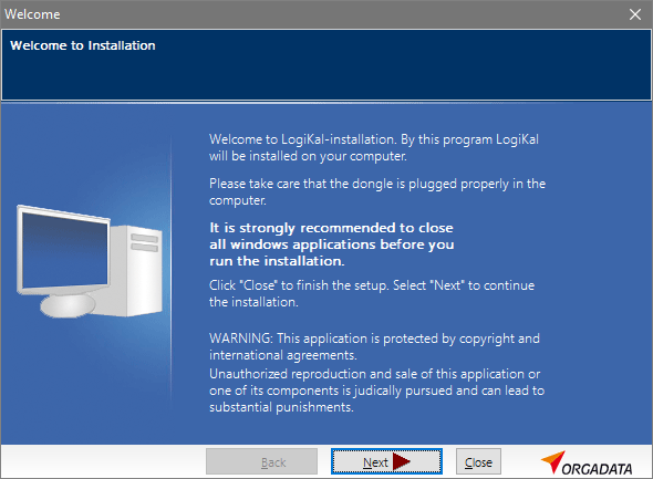
Click the „Next" button.
The installation directory is entered on the next screen. We recommend keeping the standard settings.
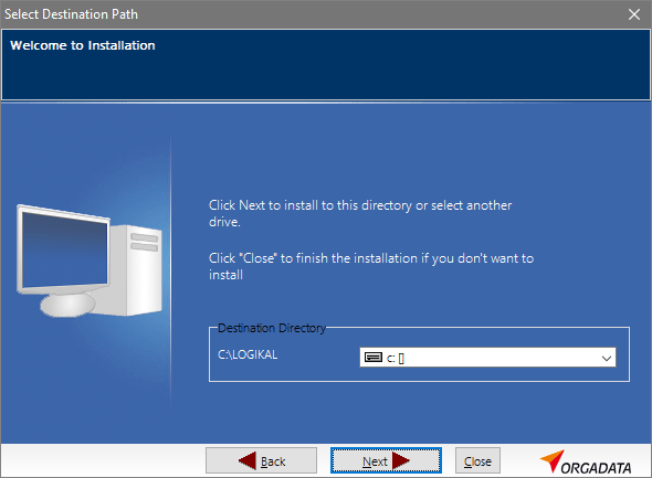
Click the „Next" button.
Determine the folder name.
We recommend keeping the standard settings.
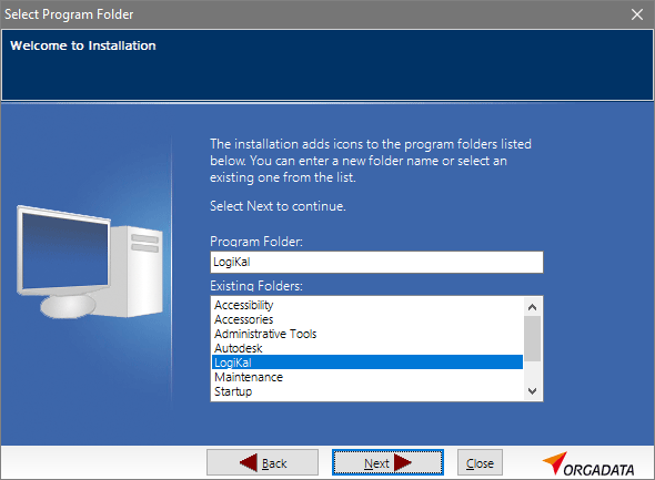
Click the „Next" button.
In the next step, you are shown an overview of the installation data.
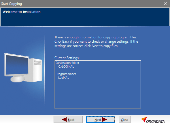
Click the „Next" button to start the installation.
The installation procedure may take a few minutes, depending on the speed of your computer.
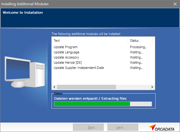
Click the „Finish" button to close the installation.
There is now a new icon on your computer's Desktop. Double-click the icon to start the program. You are automatically taken to the starting screen.
File Menu
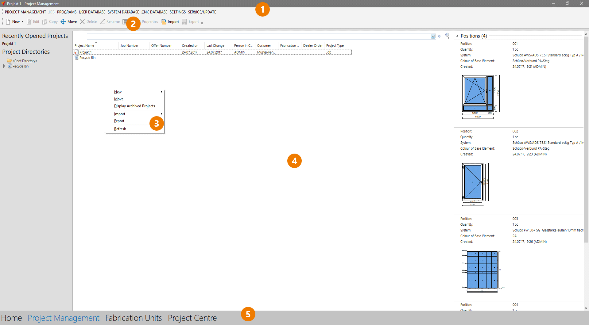
1: Toolbar
2: Context Menu
3: Content Area
4: Status Bar
5: Navigation
Home
These functions can be used to create new projects and to open and edit existing projects.
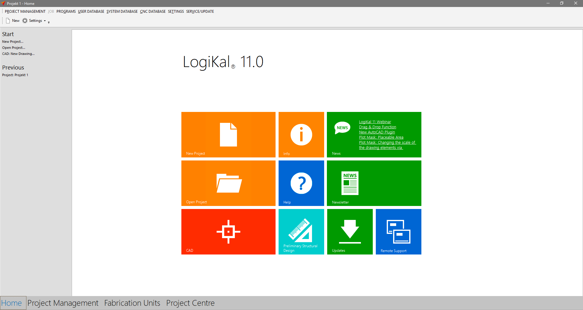
From here, you can go to the CAD and Structural Analysis.
In the support area, you can start remote maintenance and download the current updates.
Under „Help" you will find the program documentation and the latest newsletters in the Helpdesk.
Project Management
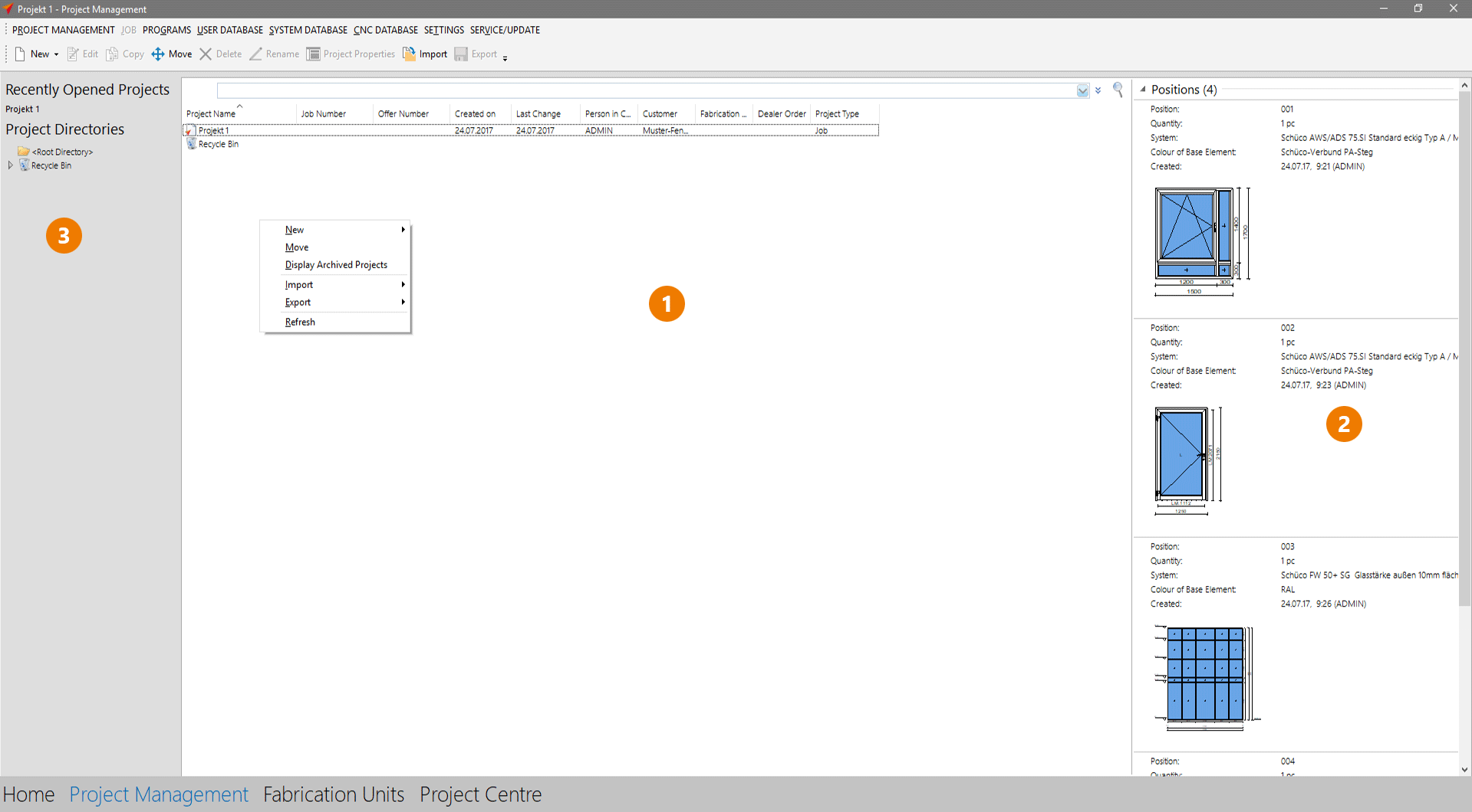
1: The central point in the project administration is the project list. All projects and their details are shown here.
2: The positions of the currently selected projects are listed here.
3: The left column shows the directory structure in which the individual projects are stored.
Creating new projects
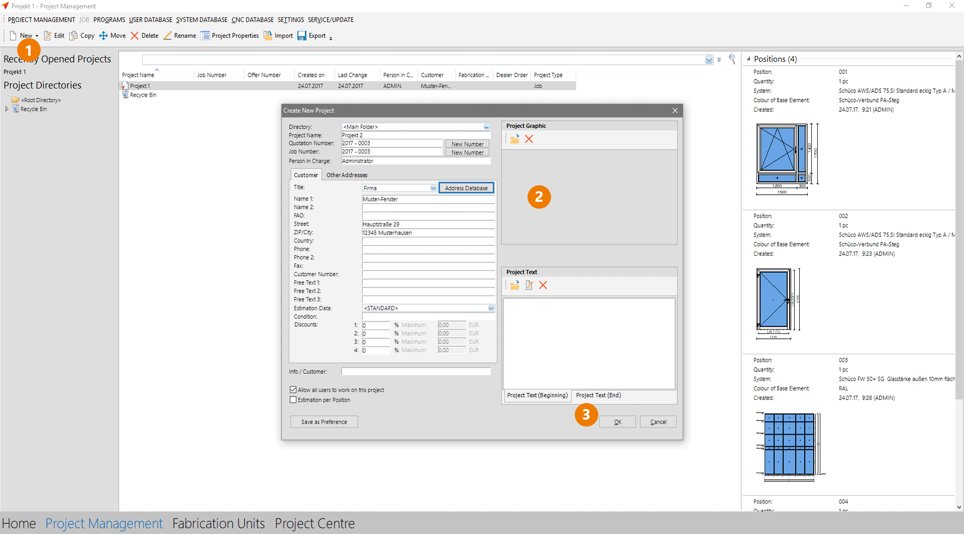
1: To create a new project, click the „New" button on the toolbar and select the „Project" option.
2: The window for project preferences opens. In the first window, enter the name of the project and enter the address data.
3: After entering the data, click the „Next" button.
In the following program windows you can make modifications for preliminary measurements for structural analysis, surfaces, colours, and glass specifications. On the last input screen, click the „Finish" button.
Creating New Positions
Once the project is created, you are automatically taken to the project centre. From here, you can create and edit the individual positions in the project.
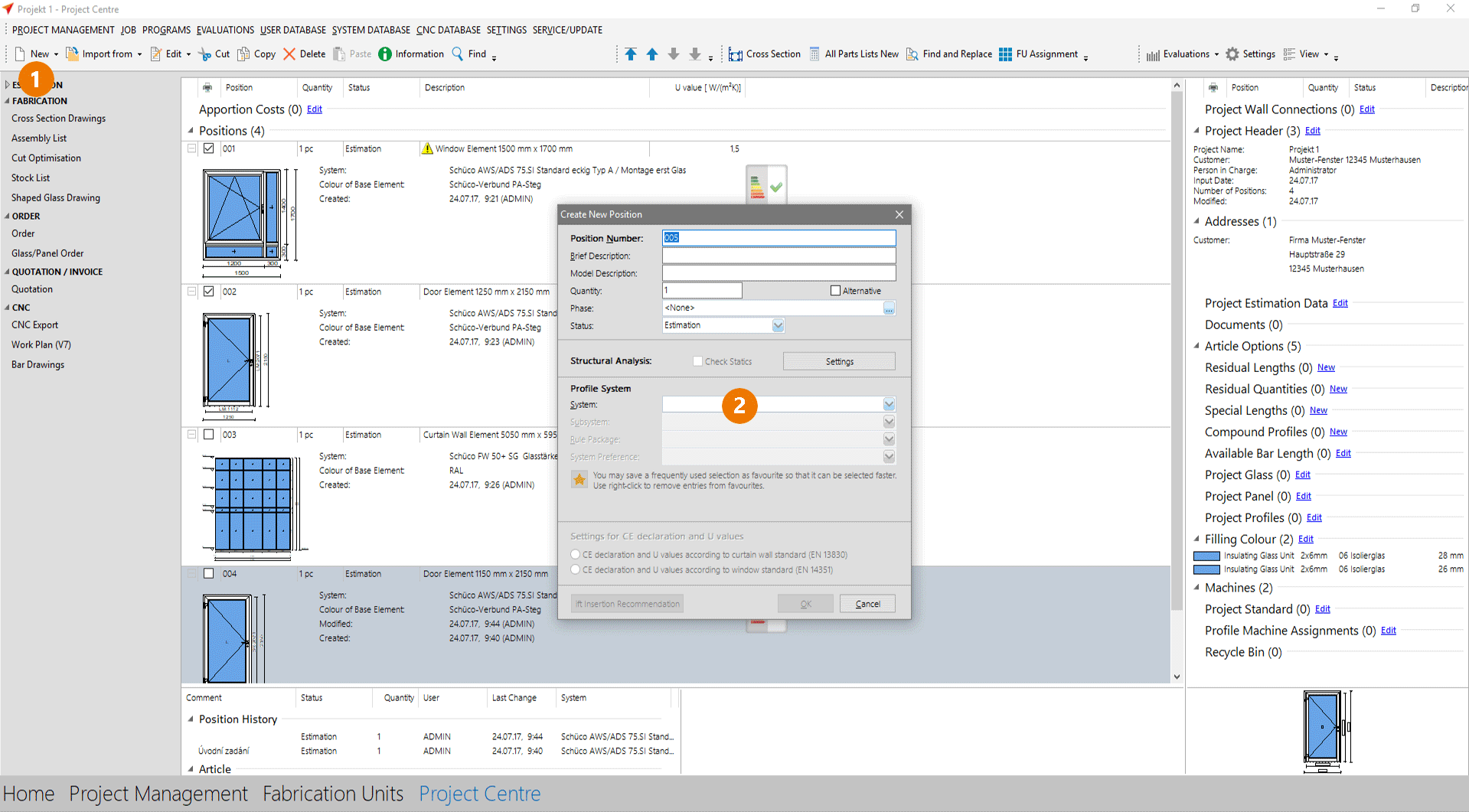
1: Click the „New" button on the toolbar, and select the „Position" option.
2: A new window opens. You will create the new position here. Enter the position number and a brief description.
Deactivate Structural Analysis.
Select a system and click the „OK" button.
Input of elements
In the input of elements you determine the geometry of the position and define all articles and specifications.
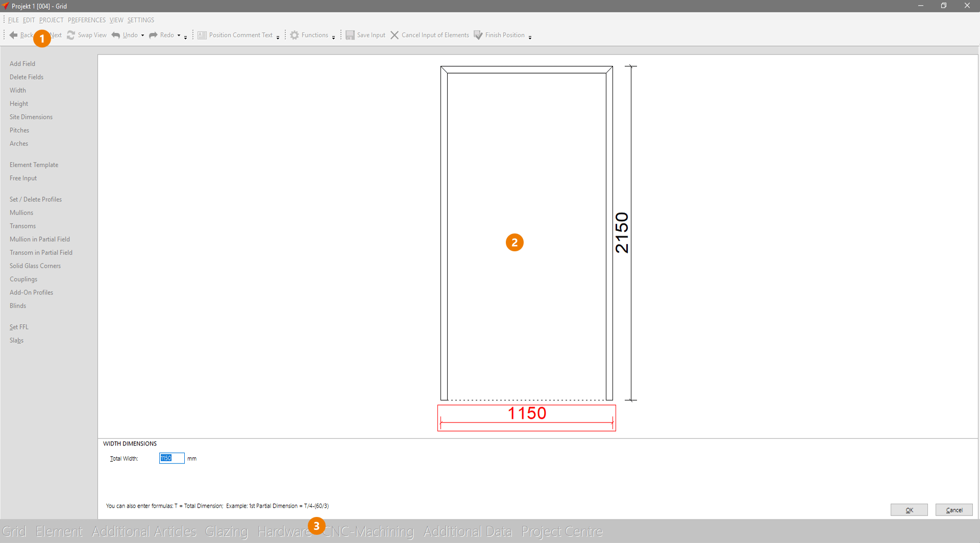
1: The properties are specified using multiple input screens. You can use the „Back" and „Next" buttons to navigate between the different input screens.
2: The position is displayed in the middle of the screen.
3: You can use the navigation at the bottom left to switch between the individual input screens directly.
Grid
In the lower area you can enter the number of width and height fields.
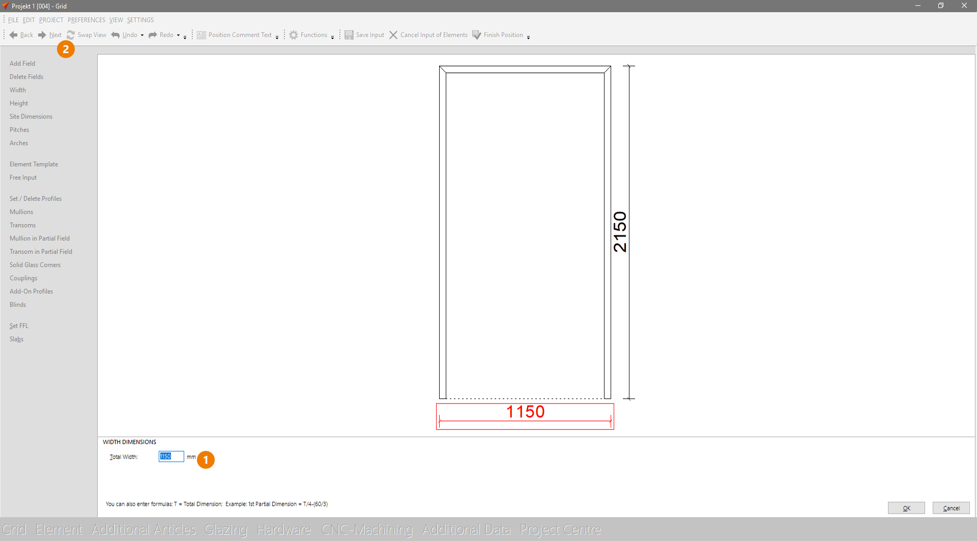
Width Field: 1 and Height Field: 1
Click „OK" or press the Enter key.
Then enter the dimensions in mm.
In this example, total width 1150 mm and total height 2150 mm.
Click the „Next" button to go to the next input screen.
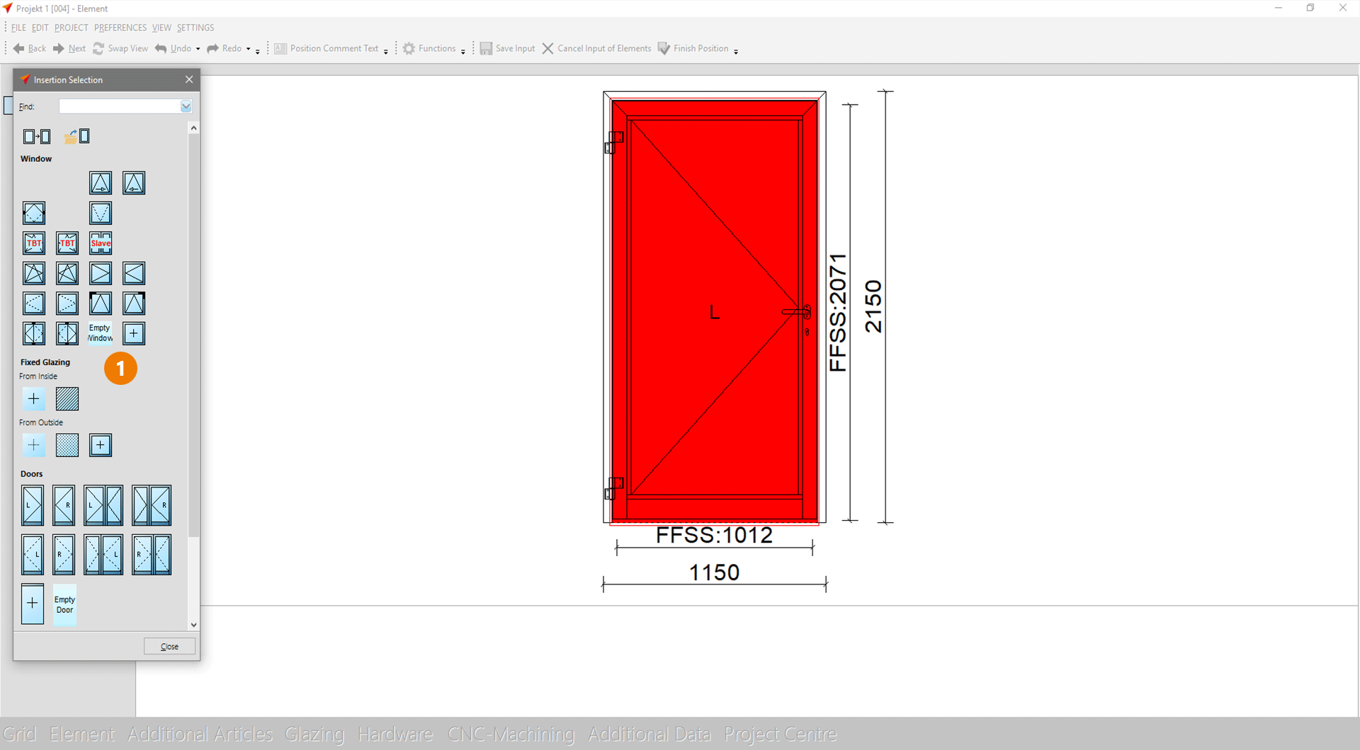
Insertions
1: Select an insert type for the position by clicking one of the icons on the left side.
Element
After you have selected the insert type, you are automatically taken to the next input screen.
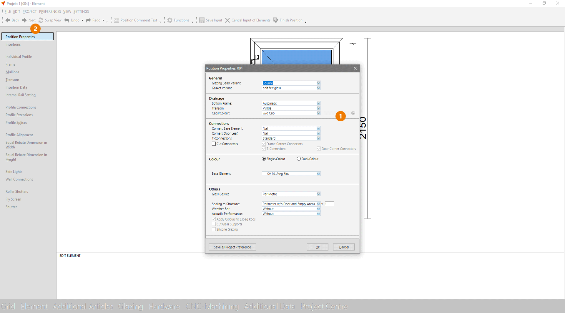
1: Here you specify all profiles, floor connections, surfaces, T-connectors, etc.
2: Click the Next button to go to the next input screen.
Glazing
In the glazing area, you modify the glass type and thickness.
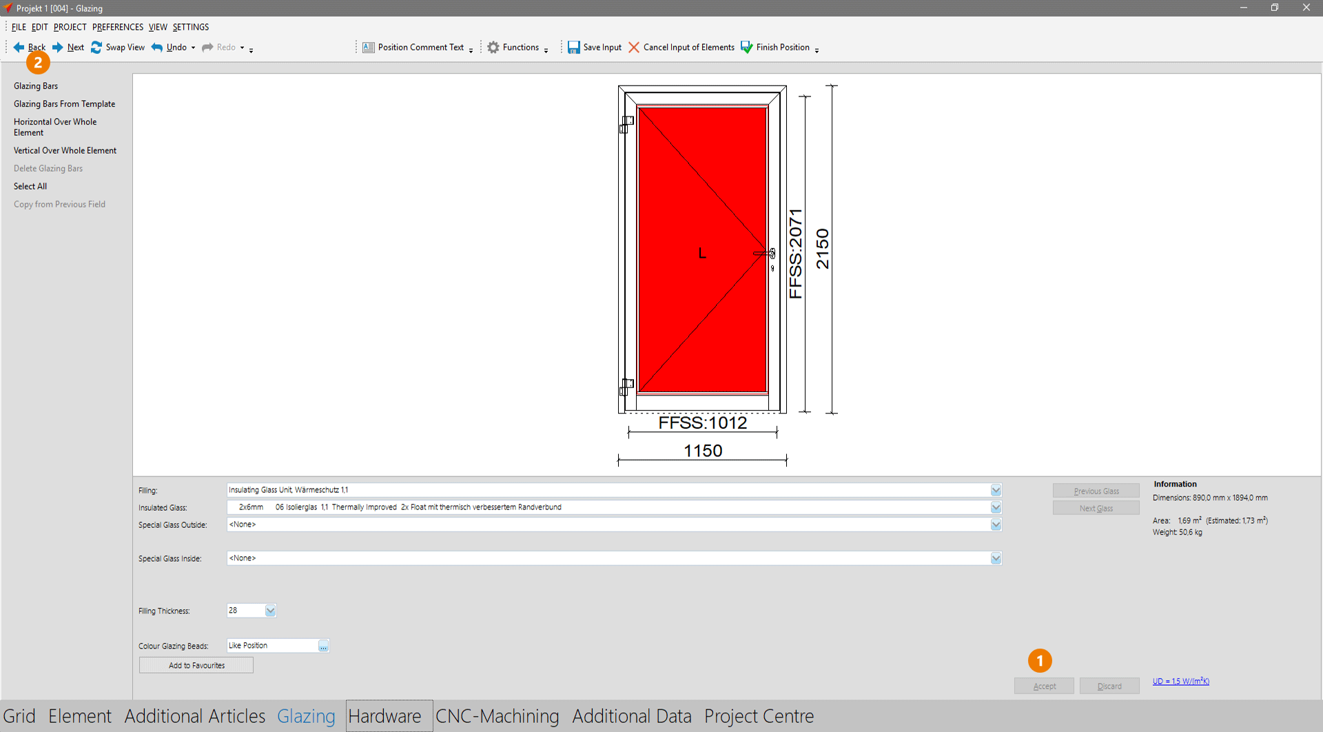
1: Click the „Accept" button to finish glass input.
2: Click the „Next" button to go to the next input screen.
Hardware
The hardware for the position is modified in this part of the program.
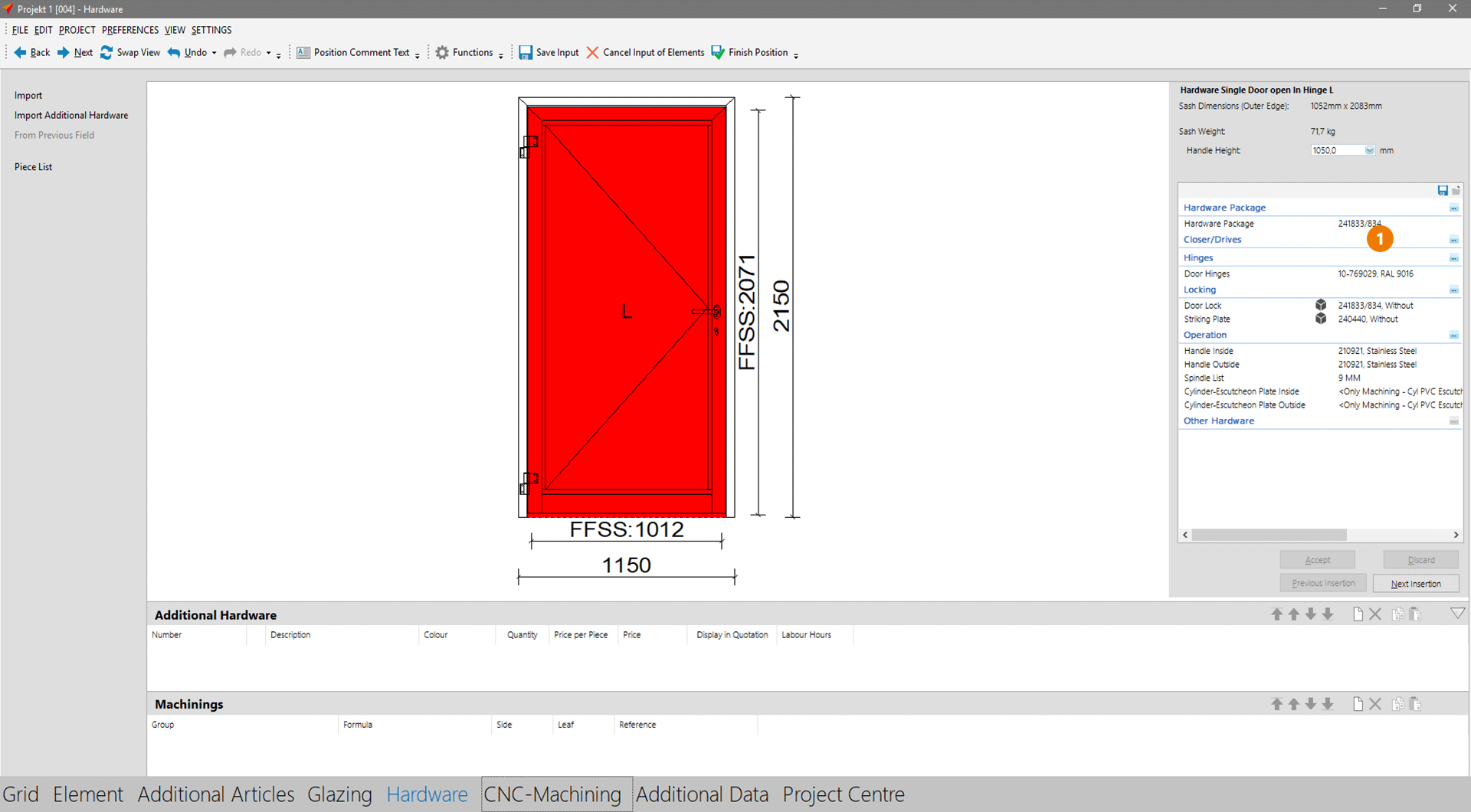
1: Enter the articles in the area on the right.
Click the „Next" button to go to the next input screen.
Additional Data
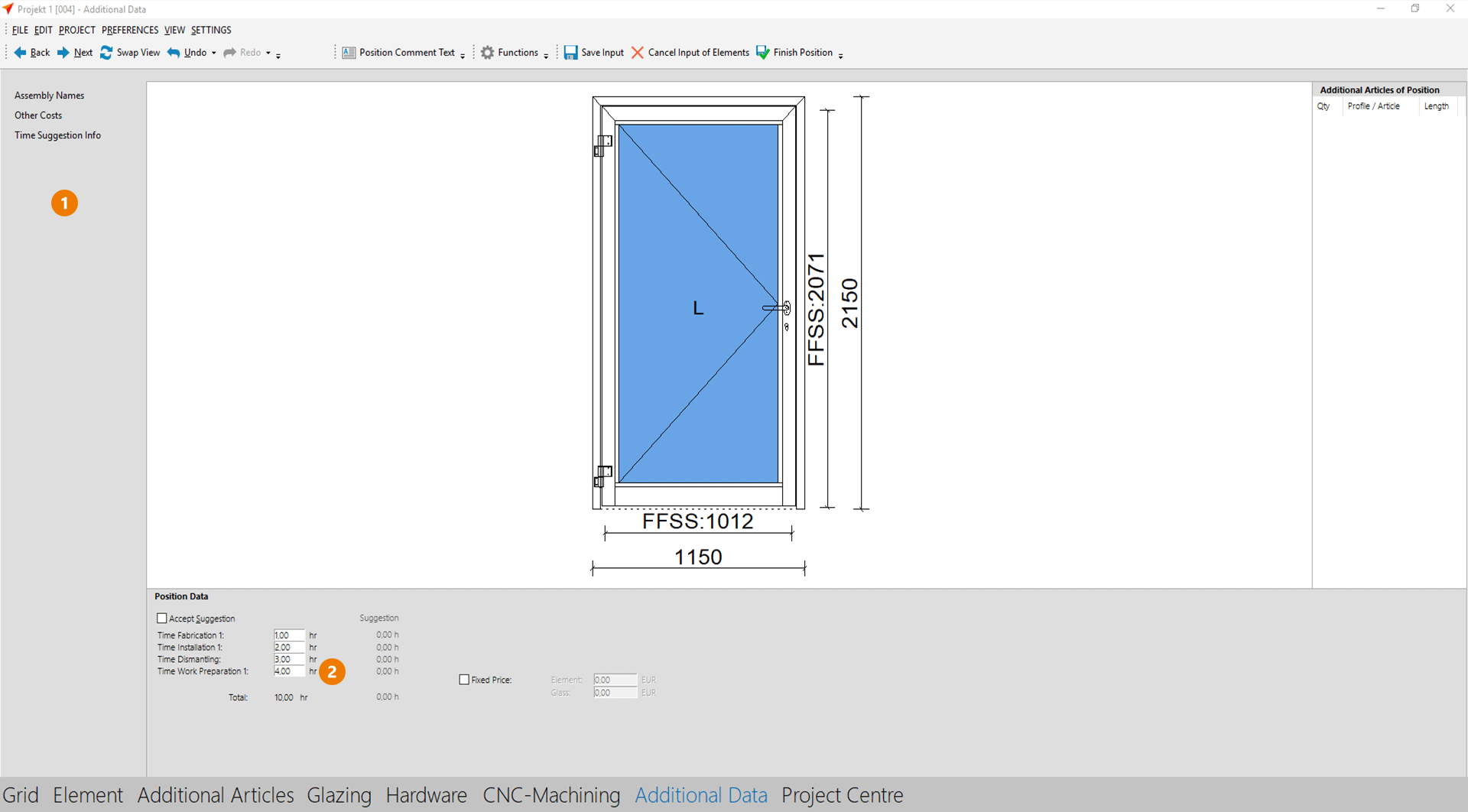
1: In the „Additional Data" area, you define assembly names and obtain details about Uw values, additional costs, and information about proposed schedules.
2: Here you can specify the fabrication time.
To finish the position, click the „Next" button and you will automatically be taken back to the project centre.
Reports
Select Positions for Reports

1: There is a checkbox in front of each position. Check this box and the Position will be included in the report.
2: Select a report
3: A window with the print functions opens. Here, you can decide whether only the selected positions or all positions should appear on the printout.
Generate Reports
Once you selected a report, the printing options appear.
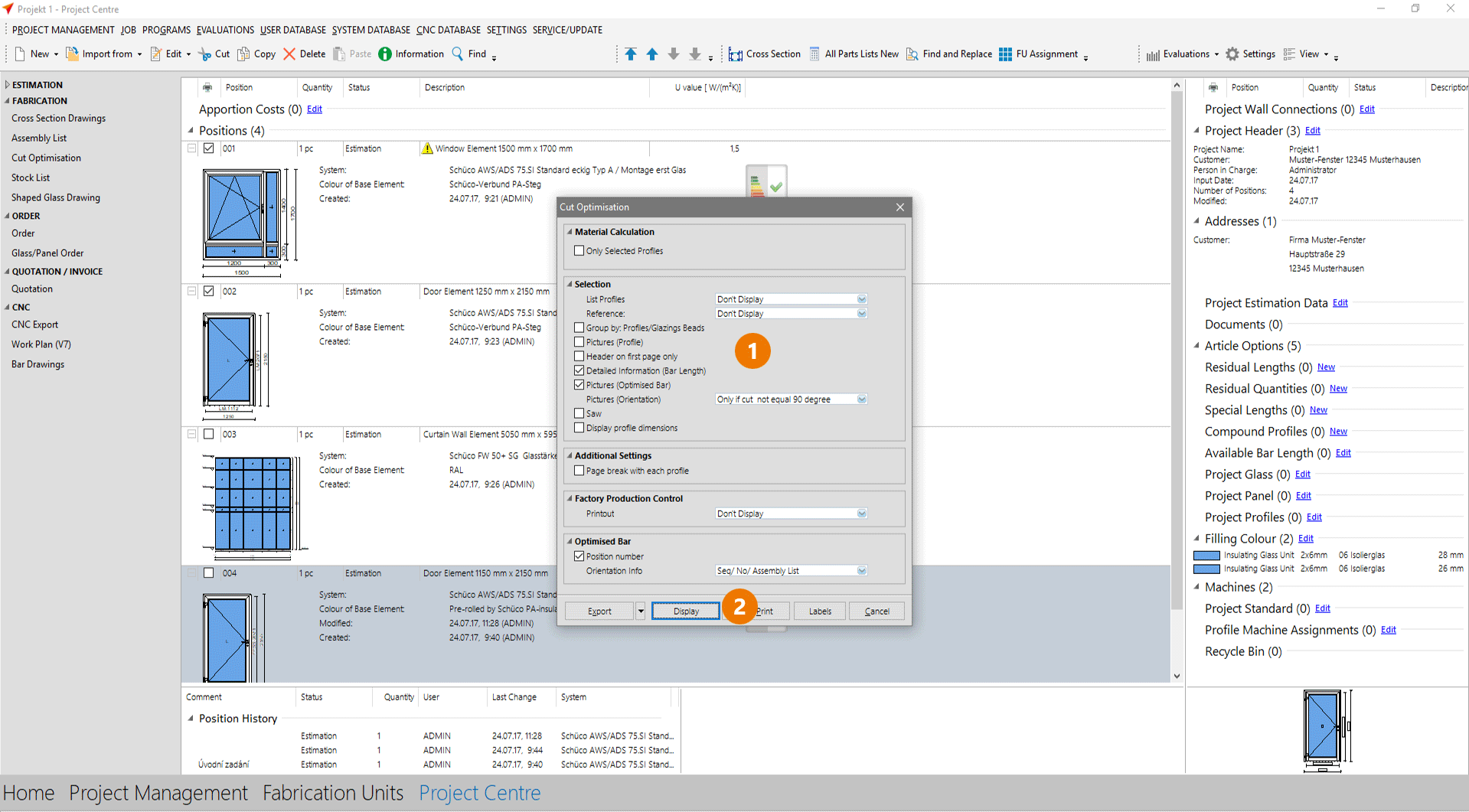
1: You can specify here which information should appear on the printout.
2: Click the „Display" button to generate the report.
Cross Section
In the cross section area you can create horizontal and vertical sections.
Select the position of the drawing and make a section line by using the mouse.
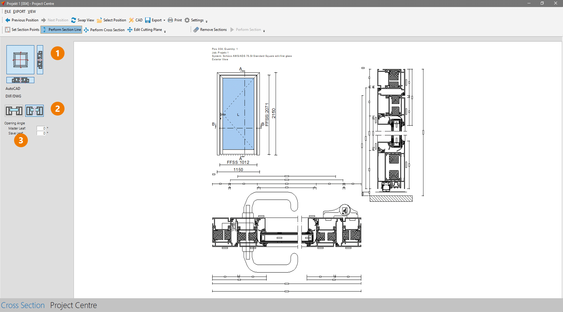
1: The buttons displayed above determine which parts of the cross section will be printed on the reports and exported to the CAD.
2: You can select between the option Actual Glass Size Display and Split Glass Size Display.
3: Under these buttons you are able to enter an opening angle for a master leaf and slave leaf.


 English (UK)