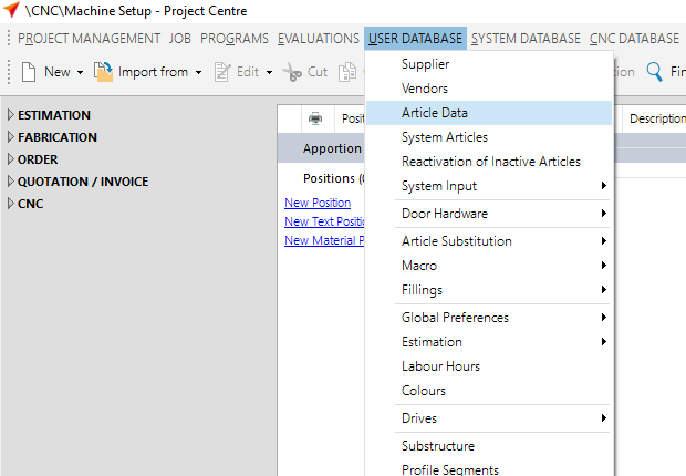
In order for the machinings to be placed on the profiles, they must be given reference points: the so-called reference points.
You can view these in the "User Database" at "Article Data" on the tab "Reference Points".
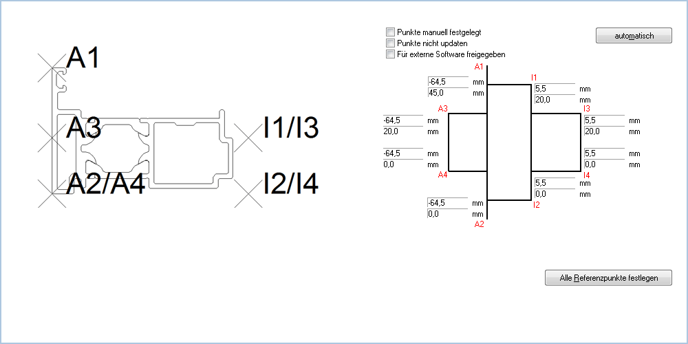
On the left side you will find the article list with the preview of the selected article.
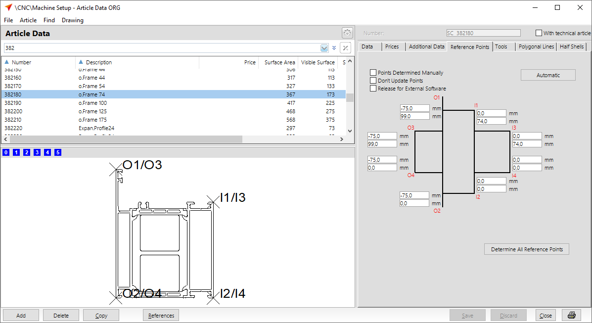
On the right side you will find a tab called "Reference Points".
Within this tab you can determine if and how the reference points should be set.
Click the "Automatic" button to have the program set the reference points. The points are always set on the left side of the profile according to the profile drawing outside (A1/A3 and A2/A4). The points inside (I1/I3 and I2/I4) are always positioned on the right side of the profile.
Activate the "Points determined manually" option if you want to set the reference points by yourself. The input fields along the sketch are available for this purpose.
During a program or database update, the settings are always overwritten. If you want to prevent this, activate the option "Don't update points".
Examples for reference points
Basic profiles
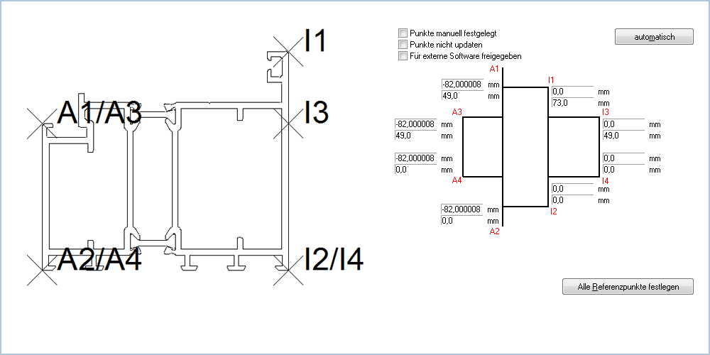
The reference points Inside 1, Inside 2, Outside 1 and Outside 2 describe the corner points of the profile structure in the area of its technical construction depth, i.e. they do not include static reinforcements or, for example, bulges on older buildings. The dimensions of these components will be described by the points inside 3, inside 4, outside 3 and outside 4.
Exception: In the case of finished frames, the additional points on the side facing the sash form an axis.
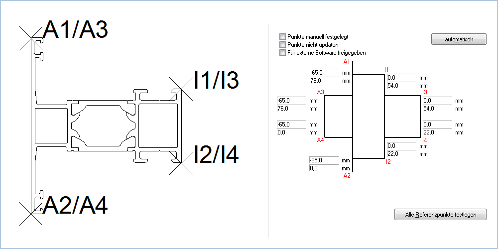
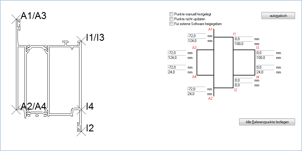
Frame profile

With the profile shown, the points Outside 1 / Outside 3, Outside 2 / Outside 4, Inside 1 / Inside 3 and Inside 2 / Inside 4 are all in the same position. They indicate the corner points of the profile structure.
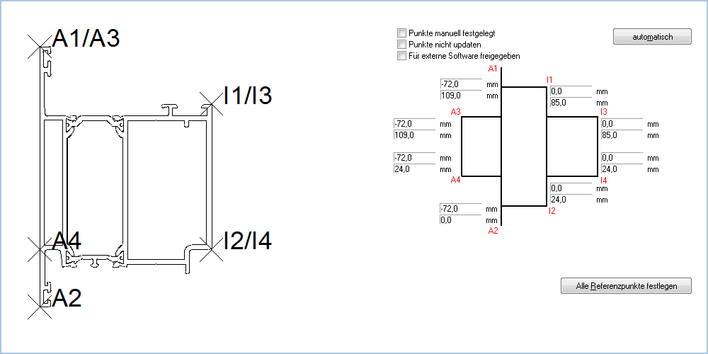
Mullion/Transom profiles
Base profile

Reinforced mullion/transom
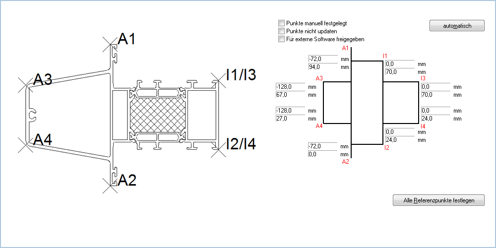
The reference points Outer 3 and Outer 4 indicate the corner points of the static reinforcement.
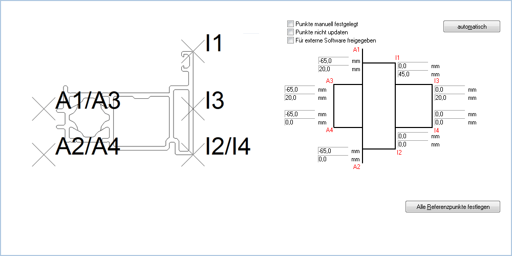
Finished frame opens outwards
The points Outer 3 and Inner 3 form an axis at the same height as the point Outer 1.
Sash profile
Similar to basic profiles, the reference points Inner 1, Inner 2, Outer 1 and Outer 2 describe the corner points of the profile structure. The additional points on the side facing away from the glass each form an axis. This axis enables later programming of lock machinings universally for inside and outside opening elements.
Sash profile

The points Outer 4 and Inner 4 form an axis at the same height as the point Outer 2.
Door leaf opening inside
The points Outer 4 and Inner 4 form an axis at the same height as the point Outer 2.
Door leaf opening outside
The points Outer 4 and Inner 4 form an axis at the same height as the point Inner 2.
Door leaf opening outside with panic function

The points Outer 4 and Inner 4 form an axis. The axis is at the same level as the axis of profiles without panic function. This means that in this case they are not at the same level as point Inside 2.
Insertion- and double-vent profiles
Insertion profile for a door opening outside

The points Outer 3 and Inner 3 form an axis at the same height as the point Outer 1.
The points Outside 2, Outside 4, Inside 2 and Inside 4 are each located at a height of 0 and in the width corresponding to the position of the profile in which the insertion profile is being inserted.
Insertion profile for a swing door
The points Outer 3 and Inner 3 form an axis at the same height as the point Outer 1.
Door double-vent profile
The points Outer 3 and Inner 3 form an axis at the same height as the point Outer 1.


 English (UK)