Create machinings
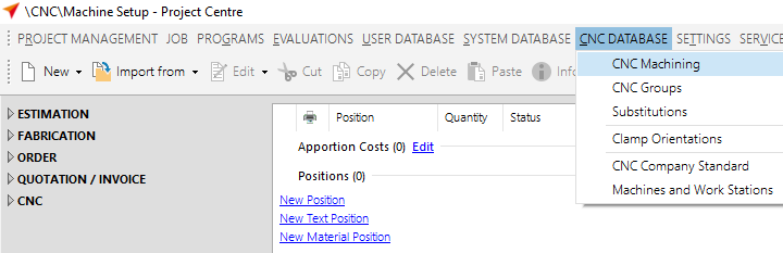
To program a new CNC machining, select the item "CNC Machining" at "CNC Database".
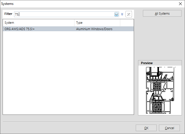
In the following screen you can select a system.
We recommend that you display the processing for all systems. To do this, click on the "All systems" button on the upper right.
The "CNC machinings" opens:
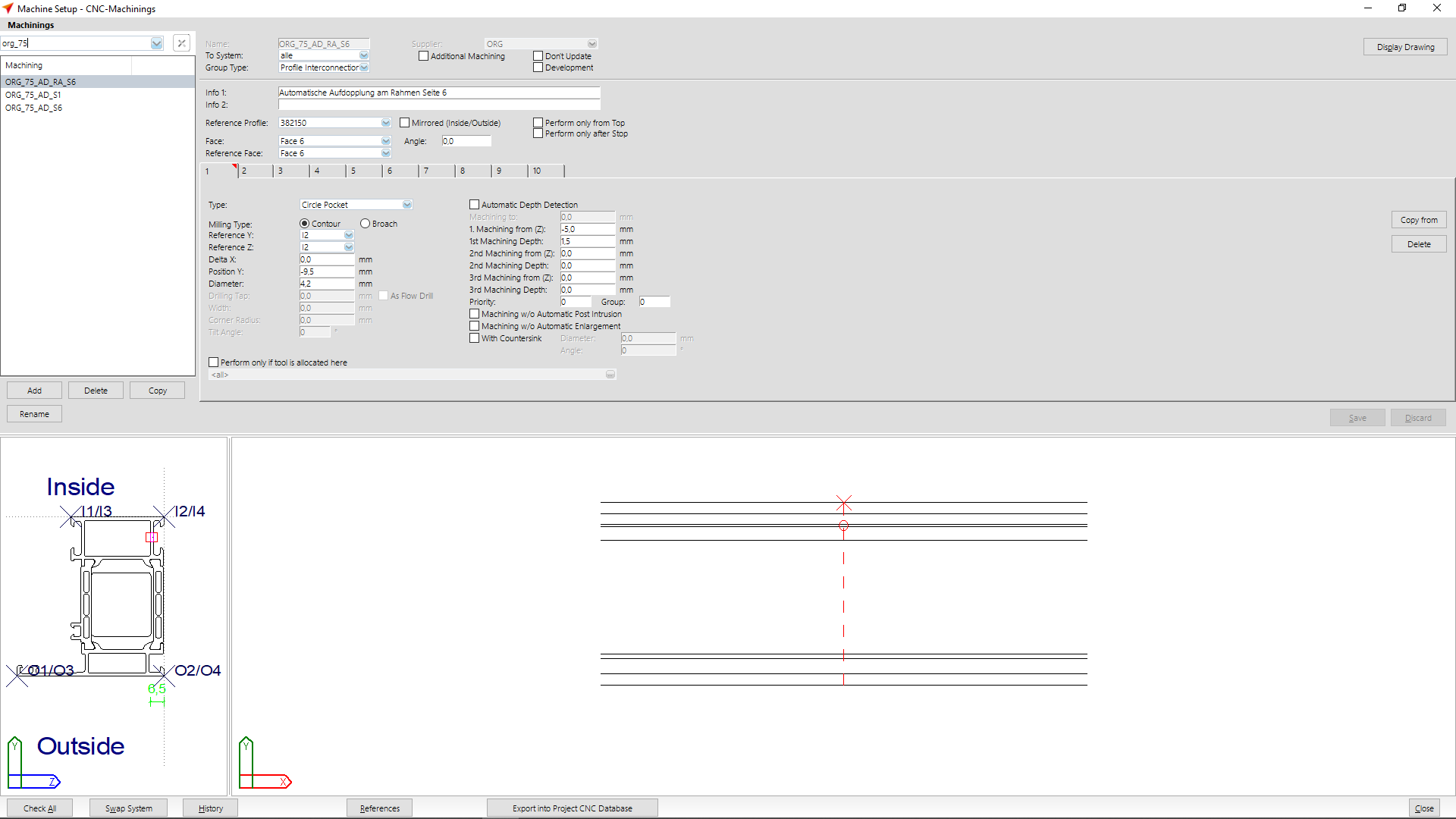
The input mask is structured into three areas:
The Preview Area is located in the lower part of the window. On the left side the profile cross-section is displayed with reference points. To the right of it, you can see how the machinings are arranged on the bar.
In the upper area, on the left hand side, there is a list of all machinings that are available for this system.
To the right of the list you enter the data for machining. The possible entries are explained below.
Enter the name of the machining operation at "Name". The list „Abbreviations in CNC machinings and groups" will show the most common abbreviations of machining names.
At "Group type" you enter the type of machining.
The following entries are available for you to select from:
- Door hardware
- Window hardware
- Corner-connector
- T-Connector
- Pressure plate sequential
- Profile interconnection sequential
- Drainage / Ventilation
- Free group
- End machining
- L/S/Dr passage
- Curtain wall bottom point
- T-Connector slant
- Corner-connector slant
- Glazing slot
- Hinge
- Striking plate
- Additional striking plate
- Striking plate for interlock
- Without
If the "Additional machining" option is activated, this machining can be directly selected in the CNC machining of the position on the bar using the import function.
You activate the "Don't update" option if you have changed a system machining and you do not want it to be overwritten by a database update.
Enter short descriptions for the machining at "Info 1" and "Info 2".
You program the machinings on a "reference profile". The advantage: The machinings can also be performed on other profiles with the same contour. Different profiles are assigned to the machinings in the machining groups. For more information, refer to the chapter "Group machinings".
At "Face" you define the side to be machined from. If you have specified face 1, 2, 3 or 6, the face in the sketch is rotated to the right. This display is independent of the position in the machine; the sketch is only used to show the machining during programming.
Turn the face of the profile so that the tool hits the profile from the right side. If you want to machine the profile on the left side, rotate the profile accordingly.
Note: On page 4 / 5 only notches are machined.
"Reference faces" are used to create machinings so that, for example, left and right doors do not have to be programmed several times. If you assign the reference faces according to the following table and the profile is inserted the other way round, for example, the machinings are automatically mirrored. For more information on this topic, see also CNC Tips & Tricks.
| Machining Type | Meaning of "Reference Side" |
|---|---|
| Corner-Connection | Outside of profiles |
| T-Connector | Passing profile: Side of adjacent profile Adjacent profile: meaningless for symmetric profiles; on asymmetric profiles the reference side is the side with the larger leg (difference inside/outside view) |
| Drainage | Upper Profile Side |
| Window Hardware | Frame and frame insertion if necessary: side to sash Sash and sash insertion if necessary: side to frame |
| Door Hardware | Frame and frame insertion if necessary: side to sash Sash and sash insertion if necessary: side to frame |
| Door Hardware Centre | Each sash to centre Each meeting stile to centre, i.e. not to the sash on which the meeting stile profile is fixed |
You need the "mirrored (Inside/Outside)" function to use machinings also on mirrored profiles. For example, the profiles in steel series are determined both normal and mirrored. In aluminium series there are profiles where the inner and outer skins are identical from the chamber and can be used accordingly for inside and outside. The mirrored profiles must accordingly also be entered as mirrored in the CNC groups.
Activate the "Perform only from top" option if the machining is only to be performed from the top, e.g. in order not to insert the angle head of your machine.
Directly below, you will find ten tabs labelled 1-10, in which each tab can be used to create a separate machining operation.
On the tab, first select the machining type at "Type".
The following machining operations are available:
- Drilling
- Circle pocket
- Slot
- Rectangle pocket
- Tap
- Notch
- T-Notch
- Screws
- Rivet nuts
- PC standard
- RC Kaba inside and outside
- Countersink
- Escutcheon plates
- Handle hole
- PC Std. w/o Fixing
- Flow Drill
- Dovetail
- Round
- Section plane
At "Milling type", you can choose whether the machining is to be carried out as an exception or if the milling cutter is only to follow the contour.
The entries for "Reference Y" and "Reference Z" define the positioning of the machinings using the reference points of the profile. This ensures that machinings can be applied to different profiles.
"Delta X": The offset of the machining to the insertion point is entered here. The following rules must be applied when entering Delta X:
| vertical profiles | + to the top |
| horizontal profiles | without insertion reference: + to the right |
| with operational reference: | + to handle side |
"Position Y" specifies the position in the Y-direction, taking into account reference Y.
You can define the dimensions of the machinings at "Diameter" (circular pocket, drilling), "Length" (rectangle pocket, slot), "Width" (rectangle pocket, slot) and "Corner radius" (rectangle pocket). You can activate the "Flowdrill" option when entering "drilling" and "tap".
The "tilt angle" (for rectangle pocket, slot) rotates the machining in top view.
In order to avoid possible collisions, activate the function "Automatic Depth Detection". The automatic depth detection is always determined from the outer edge of the profile. Enter the respective value for depth detection at " Machining to".
"1st, 2nd, 3rd machining from (Z)" indicates the start of machining. Up to the indicated position (minus the leader), the tool will move in fast feedrate.
The "machining depth" indicates the depth of the respective machining. Program only the actual machining depth with Machining Depth and Machining.
If you have entered more than one machining operation in the tabs, you can group them and assign priorities. In this way you can control the sequence in which the profile is to be machined on the machine. To do this, enter the respective number at "Priority" and "Group".
You enter the security distance (lead time) and the additional depth of machining (trail time) centrally in the CNC company standard. If the overrun is not to be performed during machining, activate the "Machining w/o automatic post intrusion" check box.
If the machining is to be carried out without the gradation entered in the CNC company standard, activate the option "Machining w/o automatic enlargement".
If you want to carry out machining with a countersink, activate the function "With countersink". Note: The additional countersink is not shown in the cross-section drawing. Furthermore, a tool of the appropriate type (countersink) must be available and the tool assignment must be activated.
Activate the function "Perform only if tool is assigned here". Click in the box below to select your machine and the corresponding tool.
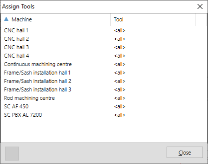
Double-click on the machine to select a tool.
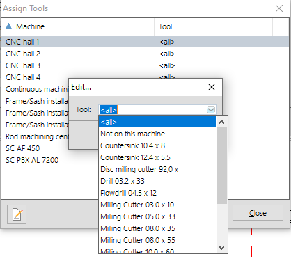
Note: The tool selected here must always be in the machine. If the tool is deactivated or renamed, the program will not execute the machining operation.
Note: If you deactivate the "Perform only if tool allocated here" function, you first have to remove the tool from the list again and reset the status of the machine's tool allocation to . Otherwise the deactivation is not accepted.


 English (UK)