In this tutorial you will learn how to create a free material package. Using the example of a blade penetration, you will learn all necessary steps.
Enter machinings
Click "CNC Database" > "CNC Machining" and select a system or click the button "All Systems".
The input window for the CNC machining opens.
Machinings for the cover cap
The first step is to create the machining for a cover cap.
Enter the name of the machining at "Name". The CNC's list of abbreviations will show the most common abbreviations of machining names.
At "Group type" select the option "Free group".
Enter a description of the machining at Info 1 and 2.
At "Reference profile" you select the basic profile by which the machining is to be executed.
At "Face", select "Face 3 (Outside)".
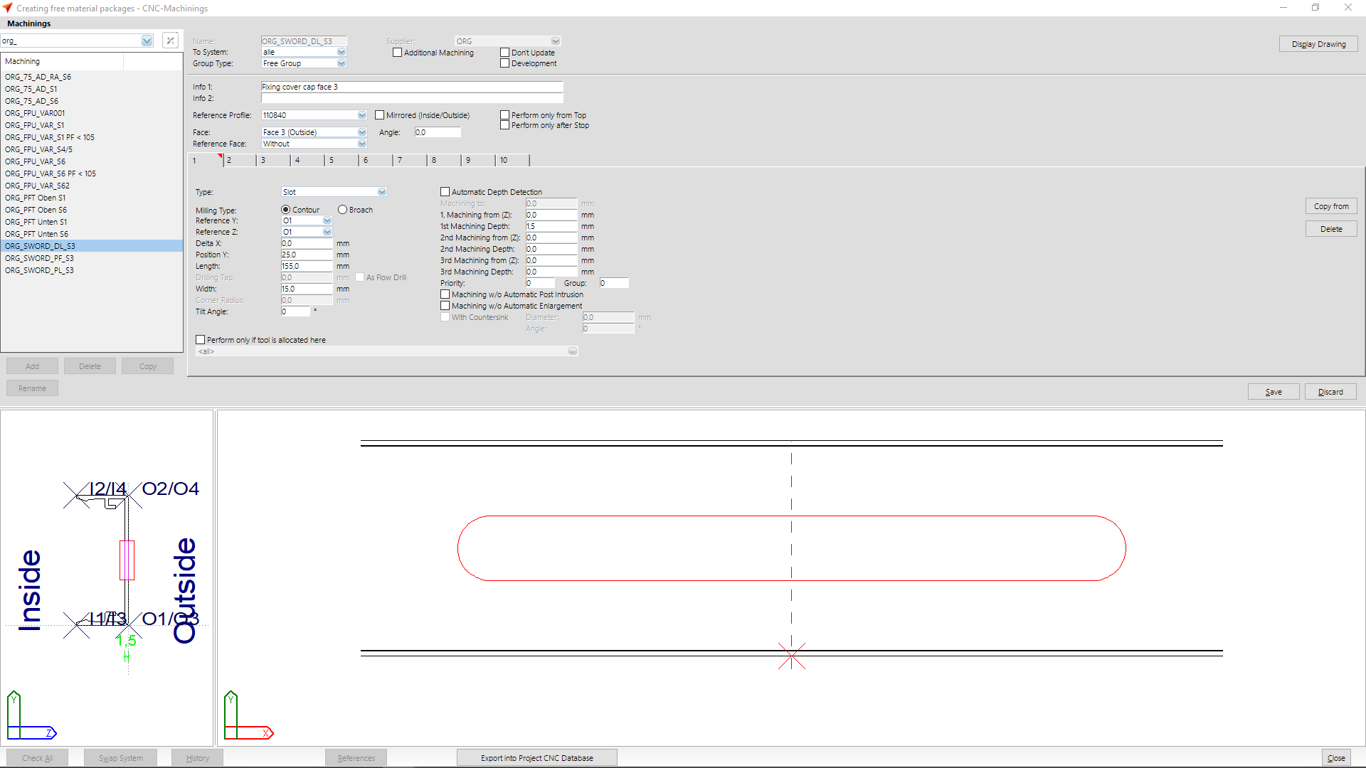
At tab "1" you enter the following data:
- Type: slot
- Milling type: contour
- Reference Y: A1
- Reference Z: A1
- Delta X: 0,0 mm
- Position Y: 25,0 mm
- Length: 155,0 mm
- Width: 15,00 mm
- Machining from (Z): 0,0 mm
- Machining depth: 1,5 mm
After you have entered the data, click on the "Save" button.
In the preview below you can see the result of your input and if necessary you can correct it.
Machinings for the mullion
The next step is to create the machinings for a mullion.
Enter the name of the machining at "Name". The CNC's list of abbreviations will show the most common abbreviations of machining names.
At "Group type" select the option "Free group".
Enter a description of the machining at Info 1 and 2.
At "Reference profile" you select the basic profile by which the machining is to be executed.
At "Face", select "Face 3 (Outside)".
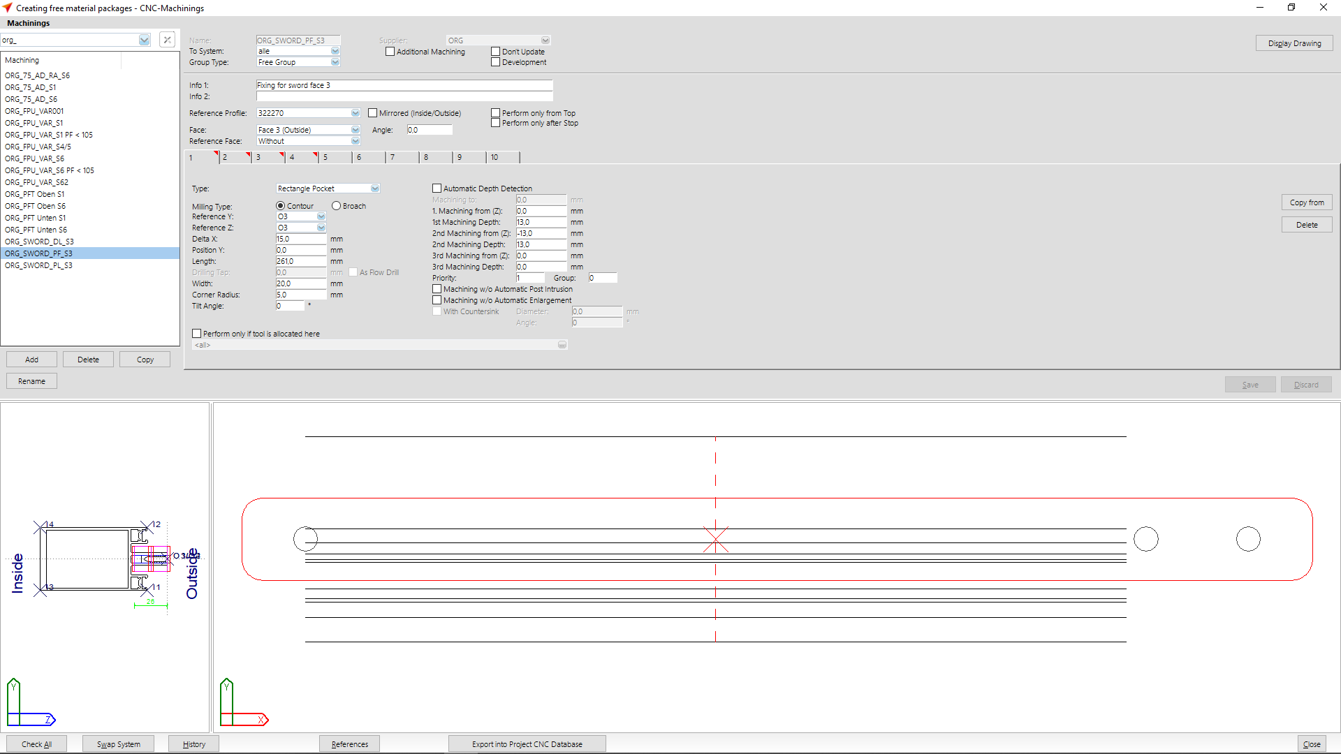
At tab "1" you enter the following data:
- Type: rectangle pocket
- Milling type: contour
- Reference Y: A3
- Reference Z: A3
- Delta X: 15,0 mm
- Position Y: 0,0 mm
- Length: 261,0 mm
- Width: 20,0 mm
- Corner radius: 5,0 mm
- Machining from (Z): 0,0 mm
- Machining Depth: 13,0 mm
- Machining from (Z): -13,0 mm
- Machining depth: 13,0 mm
- Priority: 1
Important! The sequence of machining steps in the mullion machining is determined by priorities. In this example, the rectangular pocket is given priority 1 and the machinings in the subsequent tabs 2, 3 and 4 are accordingly given priorities 2, 3 and 4.
After you have entered the data, click on the "Save" button.
In the preview below you can see the result of your input and if necessary you can correct it.
At tab "2" you enter the following data:
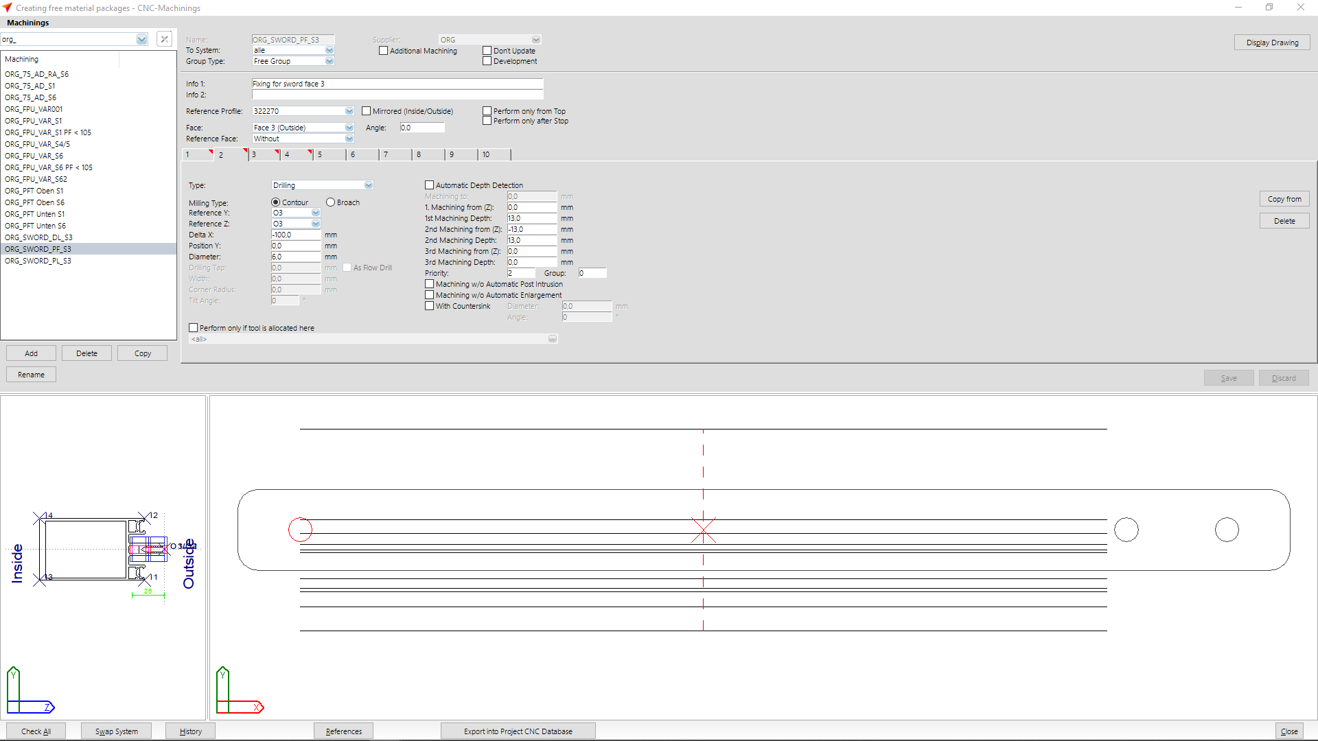
- Type: Drilling
- Milling type: contour
- Reference Y: A3
- Reference Z: A3
- Delta X: -100,0 mm
- Position Y: 0,0 mm
- Diameter: 6,0 mm
- Machining from (Z): 0,0 mm
- Machining depth: 13,0 mm
- Machining from (Z): -13,0 mm
- Machining depth: 13,0 mm
- Priority 2
After you have entered the data, click on the "Save" button.
In the preview below you can see the result of your input and if necessary you can correct it.
At tab "3" you enter the following data:

- Type: Drilling
- Milling type: contour
- Reference Y: A3
- Reference Z: A3
- Delta X: 105,0 mm
- Position Y: 0,0 mm
- Diameter: 6,0 mm
- Machining from (Z): 0,0 mm
- Machining depth: 13,0 mm
- Machining from (Z): -13,0 mm
- Machining depth: 13,0 mm
- Priority 3
After you have entered the data, click on the "Save" button.
In the preview below you can see the result of your input and if necessary you can correct it.
At tab "4" you enter the following data:
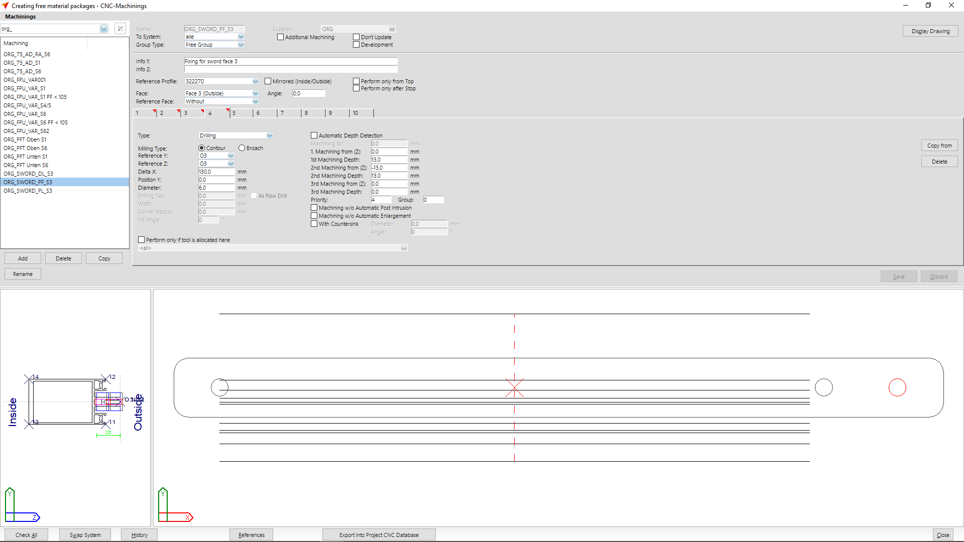
- Type: Drilling
- Milling type: contour
- Reference Y: A3
- Reference Z: A3
- Delta X: 130,0 mm
- Position Y: 0,0 mm
- Diameter: 6,0 mm
- Machining from (Z): 0,0 mm
- Machining depth: 13,0 mm
- Machining from (Z): -13,0 mm
- Machining depth: 13,0 mm
- Priority 4
After you have entered the data, click on the "Save" button.
In the preview below you can see the result of your input and if necessary you can correct it.
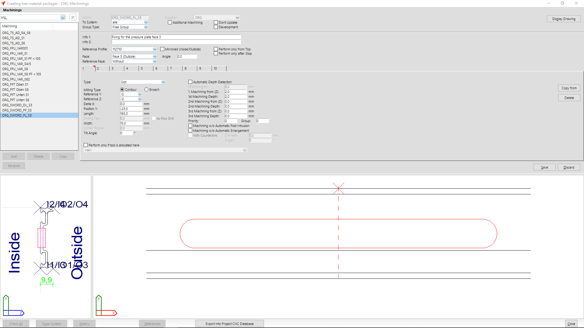
Machinings for the pressure plate
In the third step, the machining for the pressure plate is created.
Enter the name of the machining at "Name". The CNC's list of abbreviations will show the most common abbreviations of machining names.
At "Group type" select the option "Free group".
Enter a description of the machining at Info 1 and 2.
At "Reference profile" you select the basic profile by which the machining is to be executed.
At "Face", select "Face 3 (Outside)".
At tab "1" you entert he following data:
- Type: Slot
- Milling type: contour
- Reference Y: I2
- Reference Z: I2
- Delta X: 0,0 mm
- Position Y: -23,5 mm
- Length: 165,0 mm
- Width: 15,0 mm
- Machining from (Z): 2,0 mm
- Machining depth: 2,0 mm
After you have entered the data, click on the "Save" button.
In the preview below you can see the result of your input and if necessary you can correct it.
Grouping machinings
Group for mullions
Select at "CNC database" > "CNC Groups".
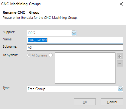
Click the "Add" button to create a new group.
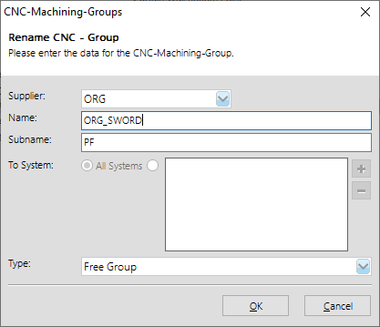
Enter the main group name at "Name".
At "Subname" you enter the more detailed name for the group.
In this example PF
PF = mullion
Determine the system in which the machining is to be used and select the option "Free group" at Type.
Click "OK".
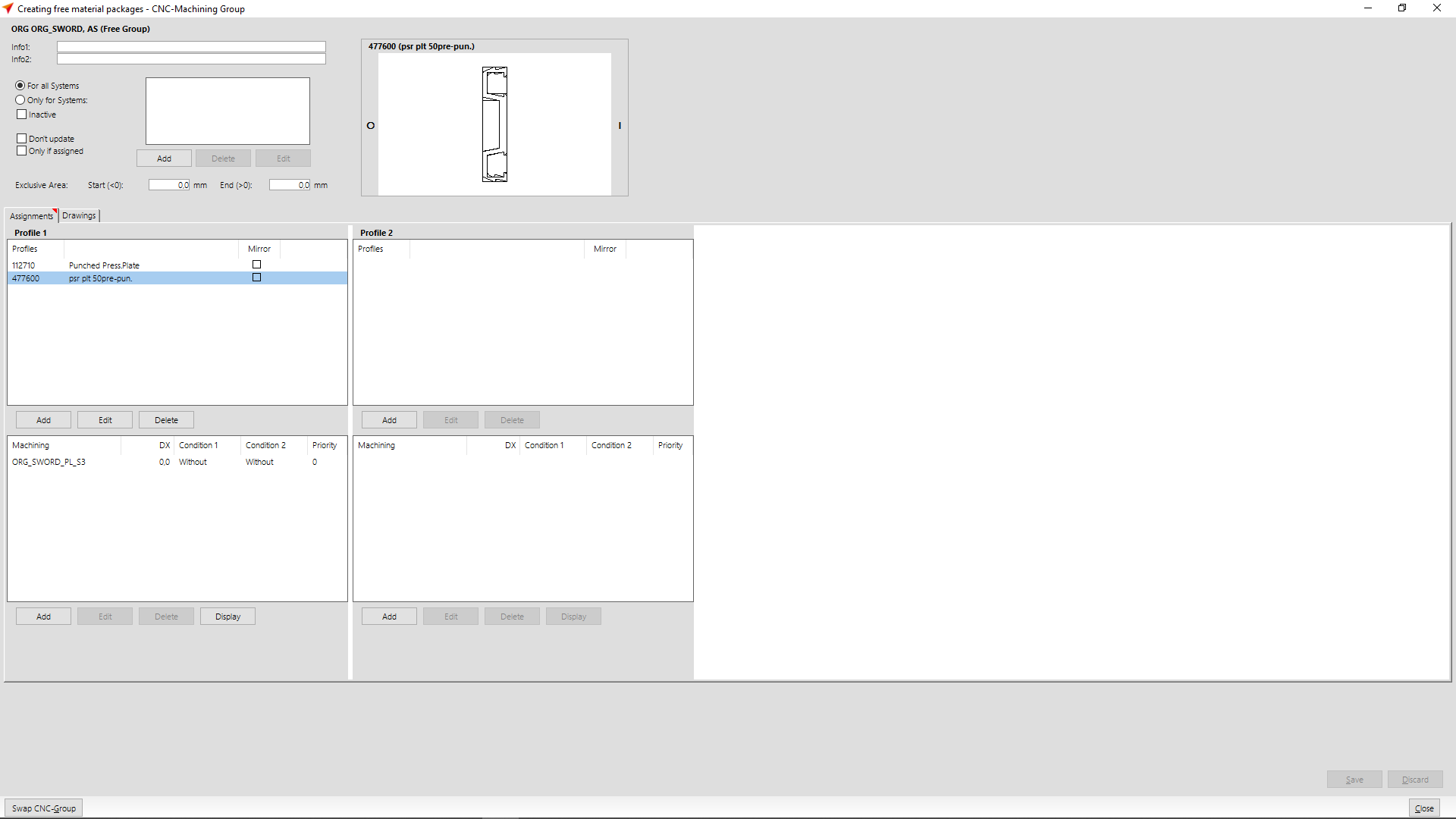
In the next window, you define the profiles and machinings to be used in this group.
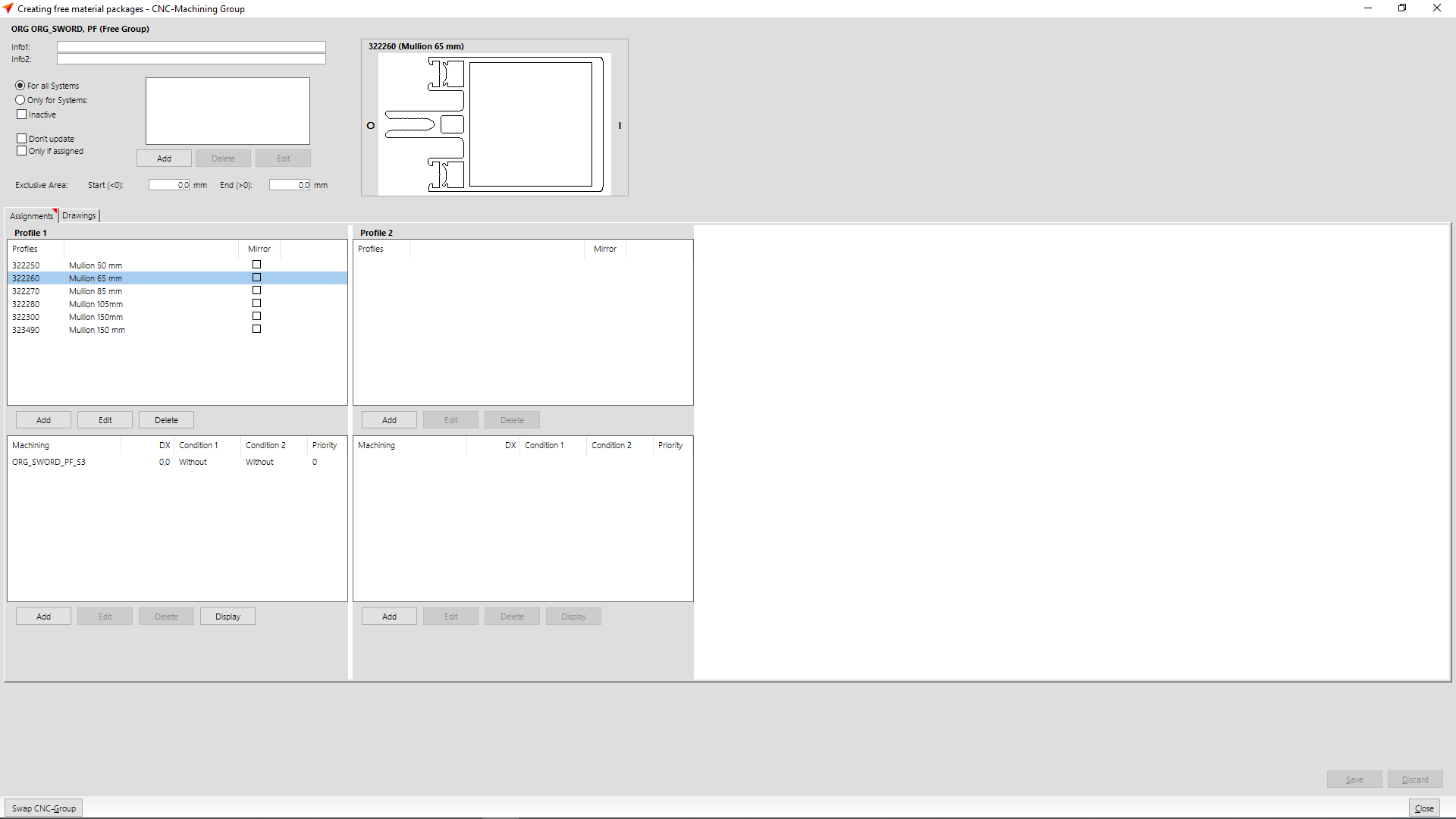
In section "Profile 1" you enter the profile numbers of the mullions for which the machinings are to be considered. In the input area below, enter the machinings that you have created for this purpose.
Group for the cover cap
Select at "CNC Database" > "CNC Groups".
Click the "Add" button to create a new group.

Enter the main group name at "Name".
At "Subname" you enter the more detailed name for the group.
In this example DL.
DL = cover cap
Determine the system in which the machining is to be used and select the option "Free group" at Type.
Click on "OK".
In the next window, you define the profiles and machinings to be used in this group.
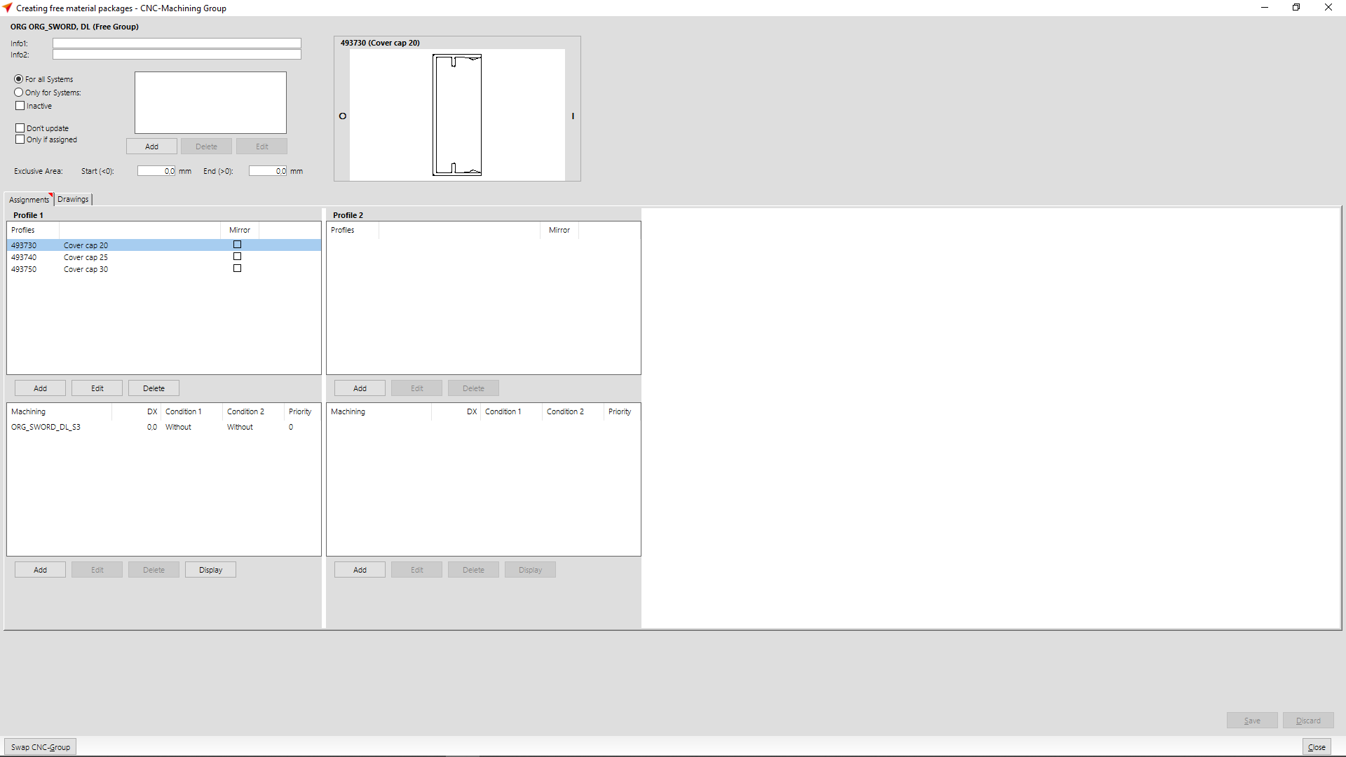
In section "Profile 1" you enter the profile numbers of the cover caps for which the machinings are to be considered. In the input area below, enter the machinings that you have created for this purpose.
Group for the pressure plate
Select at "CNC Database" > "CNC Groups".
Click the "Add" button to create a new group.
Enter the main group name at "Name".
At "Subname" you enter the more detailed name for the group.
In this example AS.
AS = pressure plate
Determine the system in which the machining is to be used and select the option "Free group" at Type.
Click "OK".
In the next window, you define the profiles and machinings to be used in this group.
In section "Profile 1" you enter the profile numbers of the pressure plates for which the machinings are to be considered. In the input area below, enter the machinings that you have created for this purpose.
Creating a material package
The next step is to create a material package.
In the Project Center, on the file menu, click "User Database" > "System Input" > "Material Packages" and select a system.
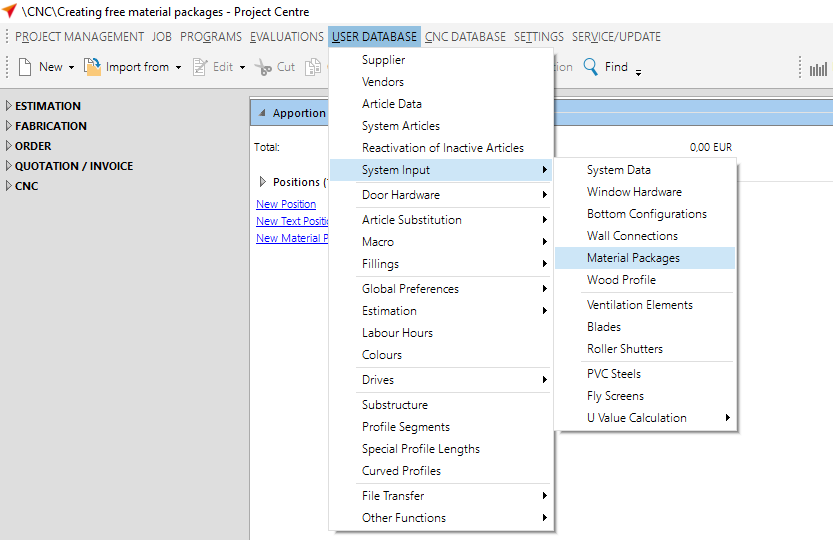
The input window for material packages opens.
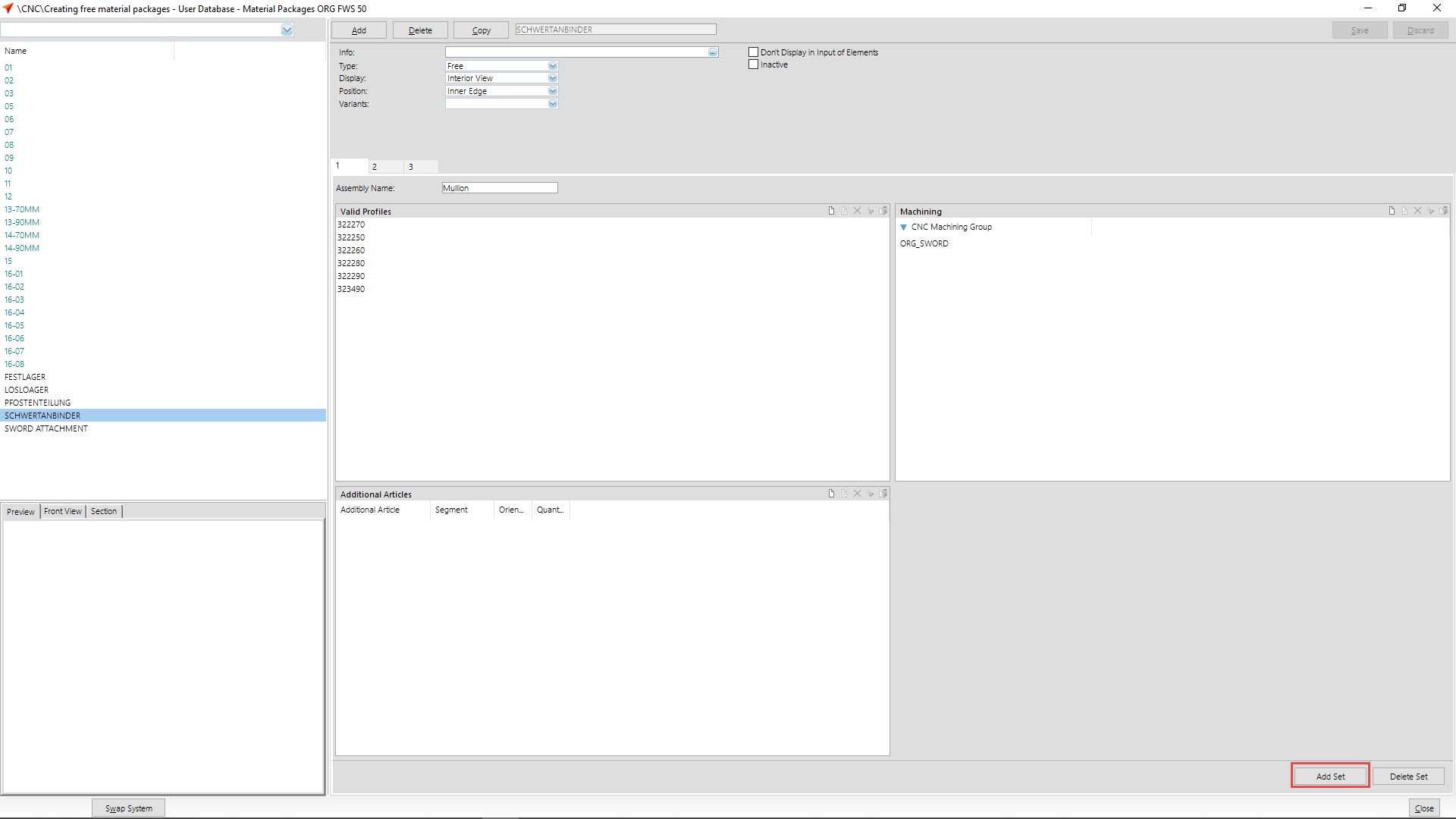
Click the "Add" button to create a new material package.
Enter a name for the material package.
Select "Free" at "Type".
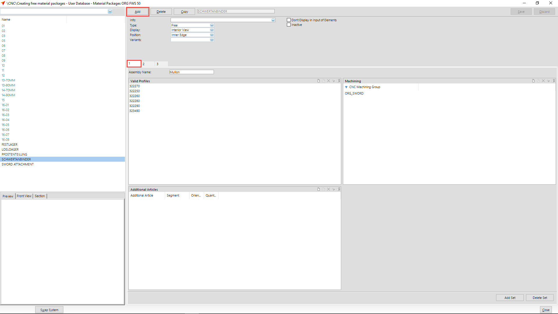
Enter the term "Mullion" at "Assembly name" in tab 1.
At "Valid profiles" you enter the article numbers of the mullions for which the material package is to be considered.
Click on "Add Set" to create a new tab.
Enter the term "Cover cap" at "Assembly name" in tab 2.
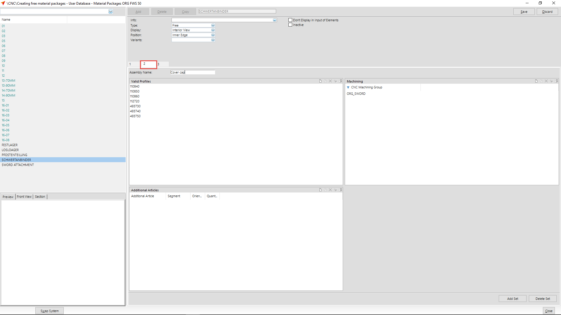
At "Valid profiles" you enter the article numbers of the cover caps for which the material package is to be considered.
Click on "Add Set" to create a new tab.
Enter the term "Pressure plate" at "Assembly name" in tab 3.
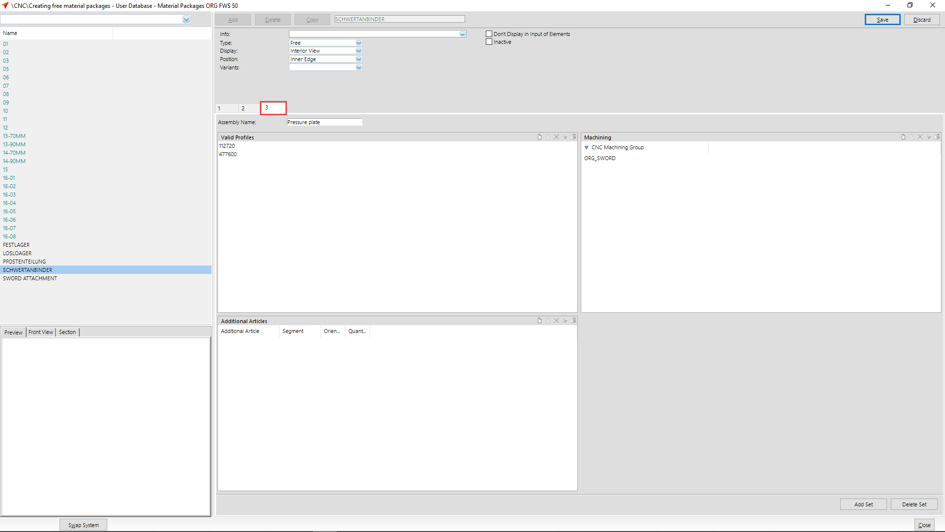
At "Valid profiles" you enter the article numbers of the pressure plates for which the material package is to be considered.
Save your input.
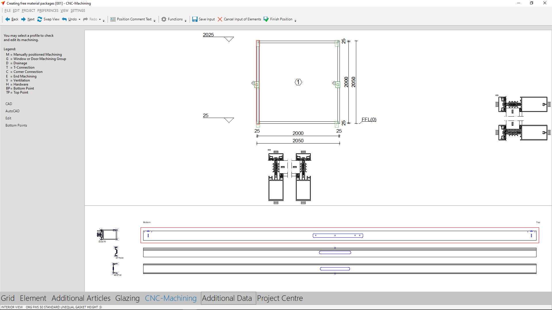
Use in element input
Create a curtain wall position in the input of elements.
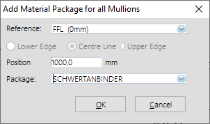
Click on "Material Packages" in the section "Element" and select the button "All".
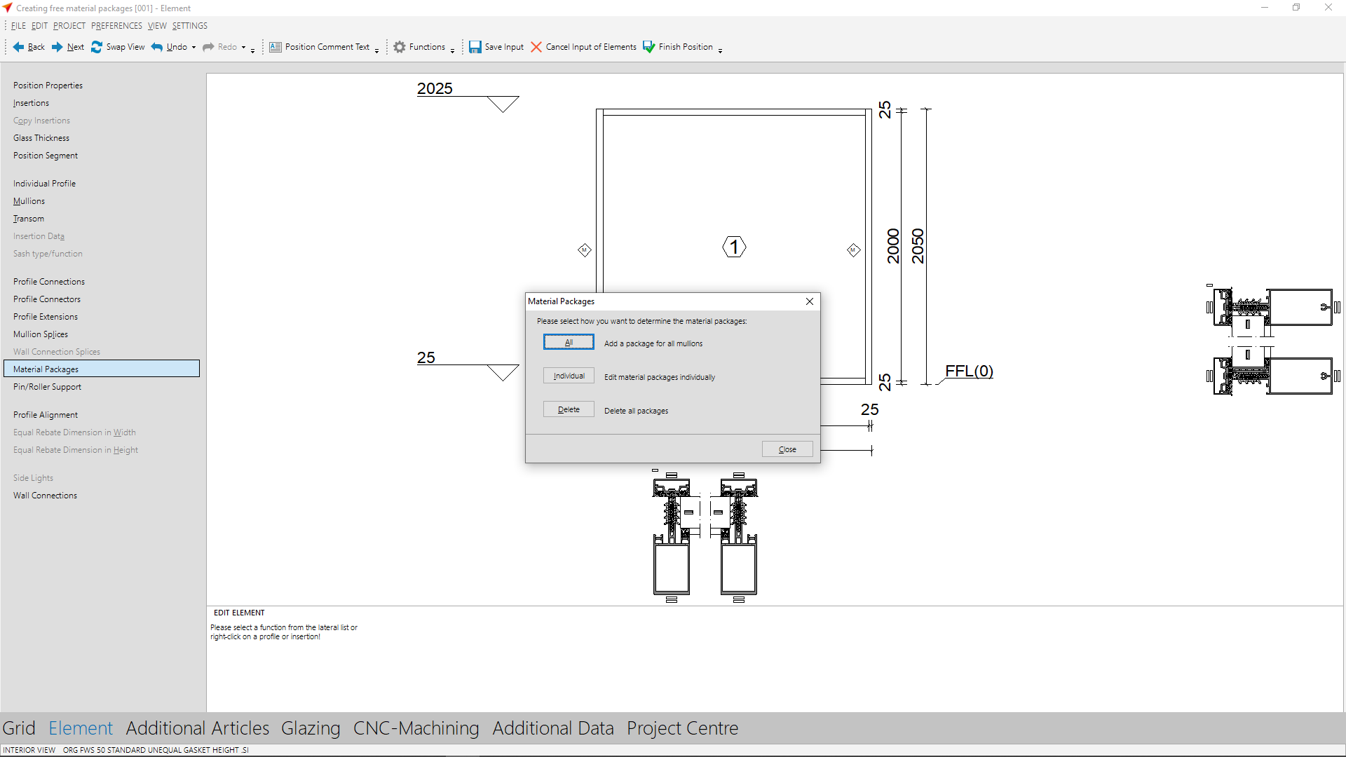
At "Reference" enter the height reference of the material package.
At "Position" you enter the positioning height of the material package.
At "Package" you select the material package you created in the previous step.
In CNC-Machining, the machining of the material package is displayed.


 English (UK)