Shortcuts in CAD
DEL: deletes selected drawings
SHIFT + DEL: removes and copies selected drawing elements
CTRL + DEL: copies selected drawing elements
SHIFT + INS: pastes copied drawing elements
SHIFT + CTRL + S: saves selected drawing elements in a file
CTRL + A: selects all drawing elements
CTRL + U: deselects all selected drawings
CTRL + C: copies selected drawing elements
CTRL + V: pastes drawing elements
CTRL + X: cuts selected drawing elements and copies them to the clipboard
CTRL + Z: Undo
CTRL + P: Print
CTRL + M: selects drawing elements. If more than one drawing is available, the mouse arrow has to be in the area of the drawing that shall be selected.
CTRL + L: creates a starting point of a line
CTRL + N: creates a new drawing
CTRL + O: Adds an additional drawing to the displayed drawing on the screen
CTRL + S: Saves a drawing to the CAD database
Pan function: By pressed scroll wheel you can move in a drawing.
User Interface CAD
The CAD user interface contains several components.
The description of the components are displayed in this picture:
On the following pages you get more information about the function of these components.
Create Toolbars
horten your mouse movement and speed up your work in CAD with the new custom toolbars.
In the CAD file menu, click on "Settings" > "User Settings."
Select the "Toolbars" tab.
You can select a toolbar from the list on the left under "Select toolbar." All functions available in the selected toolbar are listed.
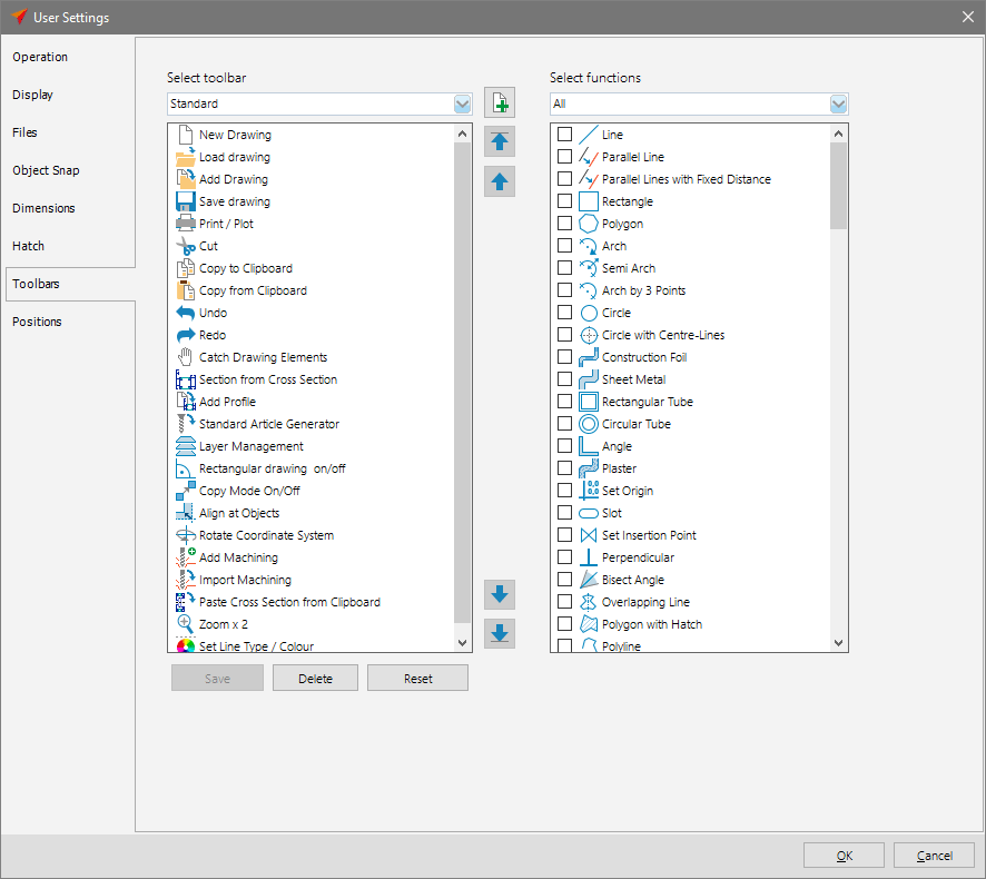
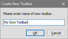
To create a new toolbar, click on the button with the green plus sign. Enter a name for the toolbar.
Now, select the functions that you wish to incorporate in your toolbar from the list on the right side.
To do so, set a check mark in front of the function.
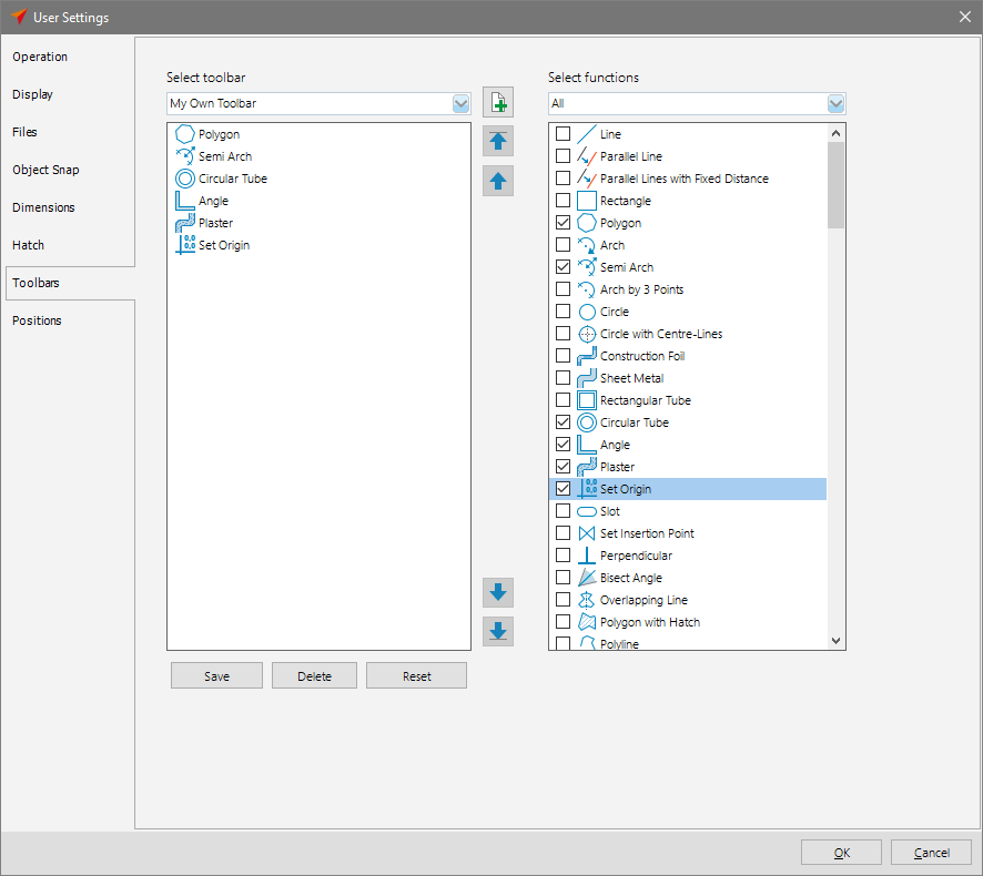
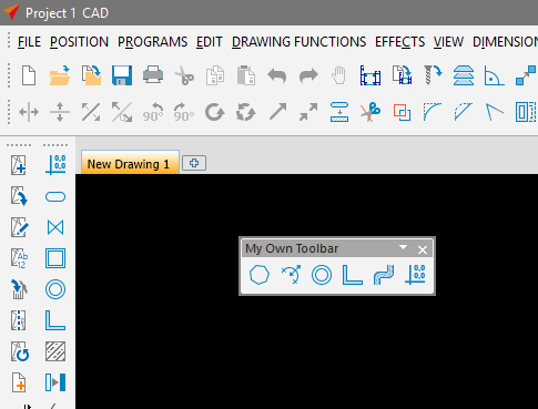
When you are done compiling your toolbar, click on the "Save" button.
Your toolbar will now appear in CAD, where you can place it in the desired location.
Standards
| Paste cross section from clipboard into CAD | |
| Undo | |
| Redo | |
| Creates a new document | |
| Loads a drawing | |
| Inserts a drawing into an existing drawing | |
| Saves a document | |
| Prints a document | |
| Cuts the selected element | |
| Copies the selected element | |
| Pastes am element | |
| Catches an element | |
| Inserts a cross section | |
| Inserts a profile into an existing drawing | |
| Opens the standard item generator | |
| Opens the layer management | |
| Orthogonal Mode | |
| Opens Settings | |
| Copies and moves selected objects | |
| Rotate Coordinate System | |
| Enables and disables object snap | |
| Imports Machinings | |
| Inserts Machinings |
Basic Drawing Functions
| Sets drawing mode to "Line" | |
| Sets drawing mode to "Rectangle" | |
| Sets drawing mode to "Polygon" | |
| Sets drawing mode to "Arch" | |
| Sets drawing mode to "Semi Arch" | |
| Sets drawing mode to "Arch by 3 Points" | |
| Sets drawing mode to "Circle" | |
| Sets drawing mode to "Circle with Centre Lines" | |
| Insert a text | |
| Inserts a text block |
Enhanced Drawing Functions
| Sets drawing mode to "Parallel Line" | |
| Sets drawing mode to "Parallel Lines with Constant Distance" | |
| Sets drawing mode to "Construction Foil" | |
| Sets drawing mode to "Sheet Metal" | |
| Sets drawing mode to "Rectangular Tube" | |
| Sets drawing mode to "Circular Tube" | |
| Sets drawing mode to "Angle" | |
| Sets drawing mode to "Plaster" | |
| Serts the origin | |
| Sets drawing mode to "Slot" | |
| Sets an insertion point | |
| Sets drawing mode to "Perpendicular" | |
| Sets drawing mode to "Bisect Angle" | |
| Sets drawing mode to "Overlapping Line" | |
| Sets drawing mode to "Polygon" | |
| Sets drawing mode to "Polyline" | |
| Sets drawing mode to "Sealing" | |
| Sets drawing mode to "Backfill" | |
| Sets drawing mode to "Lable" | |
| Inserts a hatch | |
| Inserts hatches into selected polylines and polygons |
Effects
| Converts selected elements into lines | |
| Converts selected lines into arches | |
| Optimises drawing | |
| Sets a cross section | |
| Lengthems line at other line | |
| Closes corners | |
| Rounds corners | |
| Enables "Mirror Horizontally" mode | |
| Enables "Mirror Vertically" mode | |
| Enables "Mirror Free" mode | |
| Enables "Mirror at Line" mode | |
| Optimise Polygon | |
| Cut Rectangle | |
| Closes Corners | |
| Chamfer Corners | |
| Lengthen Line | |
| Proportional Scaling | |
| Free Scaling | |
| Edit scale | |
| Set scale | |
| Detect polygon | |
| Edit polygon | |
| Explode arch into polygon | |
| Copy Properties | |
| Copy onto another layer | |
| Draw Sight Lines | |
| Lengthen Selected Object at Line | |
| Trim Selected Objects | |
| Enables "Rotate Perpendicularly Left" mode | |
| Enables "Rotate Perpendicularly Right" mode | |
| Enables "Rotate" mode | |
| Enables "Multiple Rotate" mode | |
| Enables "Move" mode | |
| Enables "Multiple Move" mode | |
| Enables "Stretch Objects" mode |
Dimensions
| Sets horizontal dimension | |
| Sets vertical dimension | |
| Sets oblique dimension | |
| Edits dimension | |
| Edits selected dimension | |
| Sets parallel dimension | |
| Sets radial dimension | |
| Sets diameter dimension | |
| Sets angle dimension | |
| Sets arch dimension | |
| Sets dimension scale |
Guide Lines
| Shows or hides guide lines | |
| Sets a horizontal guide line | |
| Sets a vertical guide line | |
| Sets mode to "Guide Line" | |
| Sets mode to "Guide Circle" | |
| Sets mode to "Guide Arch" | |
| Sets mode to "Parallel Guide Lines" | |
| Sets mode to "Tangent Guide Line" | |
| Sets mode to "Guide Line Fence" | |
| Sets mode to "Delete Guide Lines" | |
| Sets mode to ""Delete All Guide lines" | |
| Sets Guide Line Grid |
Mark
| Enables selection mode "Select" | |
| Enables selection mode "Select to intersection point" | |
| Enables selection mode "Select Area" | |
| Selects all objects | |
| Inverts Selection of all Objects | |
| Deselects all objects | |
| Sets current line type and colour | |
| Deletes selected objects | |
| Enables double zoom mode |
Move Toolbars
Click with pressed left mouse key on the dotted line on the left of the toolbar. You are able to change the position of the toolbar.

Enable Icons
You may determine which icons shall be displayed in the toolbar.
Therefore click on the arrow on the right of the toolbar. A menu appears. Here you are able to activate and deactivate the different icons.

Statusbar
The status bar is on the bottom of the screen. Here you find information while you are creating a drawing e.g. the coordinates of the cursor and different drawing functions.
File Menu
The file menu is on the top of the screen and contains all functions and setting of the Logikal CAD.
Click with the mouse on a item in the file menu, to display the list of the different options.
You are also able to use the keyboard. Press the ALT key and the underlined character of the menu item.
Example: If you want to create a new drawing, press the ALT key and F. The file menu appears. Now press the key N and a blank page appears on the drawing area.
Context Menu
By using the context menu you are able to get quick access on all relevant functions while creating a drawing.
You may display the context menu by right click in the drawing area.
PAN and Zoom Function
Use the zoom function to enlarge or to reduce the view of drawing.
Move the scroll wheel up to zoom in.
Move the scroll wheel down zoom out.
By using the PAN function you are able to move in a drawing. Therefor press the scroll wheel of the mouse and move it to the desired position.
Element input, CAD and estimation interaction
With Logikal, CAD and estimation are integrated even more tightly.
For example, you can incorporate your elements into a CAD installation drawing as early as the design phase. To do so, simply add your item views and sections to your drawing.
Modifications made in the Input of Element in Logikal are immediately updated in the drawing.
You can also edit the elements directly from the drawing.
This is then updated across all workplaces.
This significantly speeds up cooperation at your company and prevents mistakes.
All personnel will have access to the same version of the element's design.
This interplay also works when a new CAD system is integrated into your workflow.
Here too, modifications are immediately forwarded from CAD to Logikal and from Logikal to CAD.
In addition, ERP systems use the same connection to keep materials, resource planning, estimations etc. up to date – no matter where or in what linked program the changes are made, all other instances will be current.
Located in the file menu of CAD is the "Position" menu.
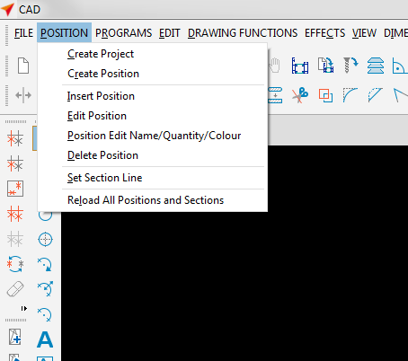
This menu allows you to create completely new projects and positions directly in CAD.
Positions can be added to the drawing area and edited.
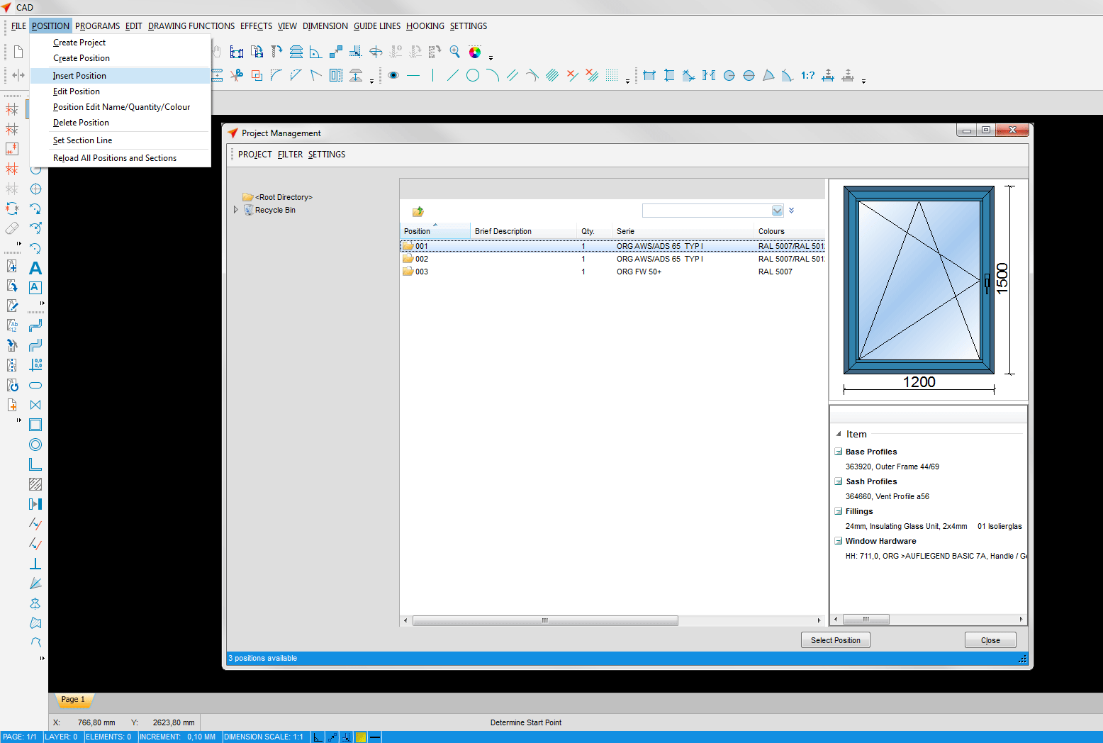
To insert the item, open CAD and click on "Position" -> "Insert Position" in the file menu. Select an item from the list.
To generate a cross-sectional view of this position, click on "Position" -> "Set Section Line" in the file menu. Draw the cutting line with the left mouse button pressed.
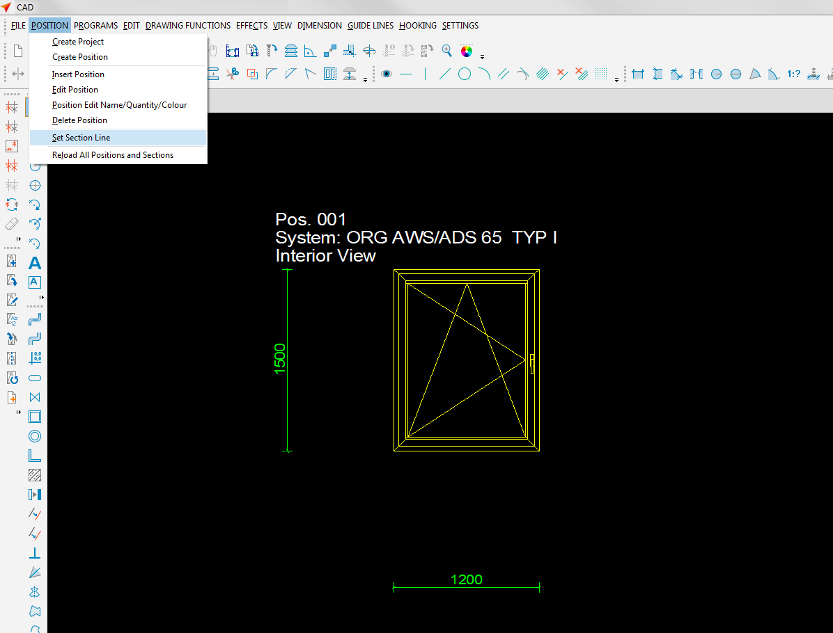
Place the sectional drawing on the drawing area by pressing the left mouse button.
The sectional view can be changed by clicking the right mouse button.
Dimensional changes can be made directly via "Settings" -> "User Settings" -> "Positions". This allows you to modify the size ratio between the drawing elements using the scale settings for view and editing.
Previous Function Call in the Context Menu
Simplify the handling in CAD and draw even faster by directly accessing the most recently selected function with just a single mouse click.
In CAD, open the most recently accessed function by clicking the right mouse button: it is always listed at the very top of the context menu.


 English (UK)