Enter machinings
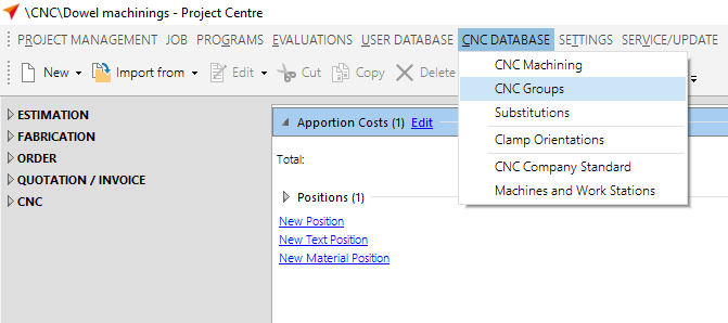
Click "CNC Database" > "CNC Machining" and select a system or click the "All Systems" button.
The input window for the CNC machining opens.
Anchor machining Outer Frame face 1
The first step is to create the machining for an outer frame on face 1.
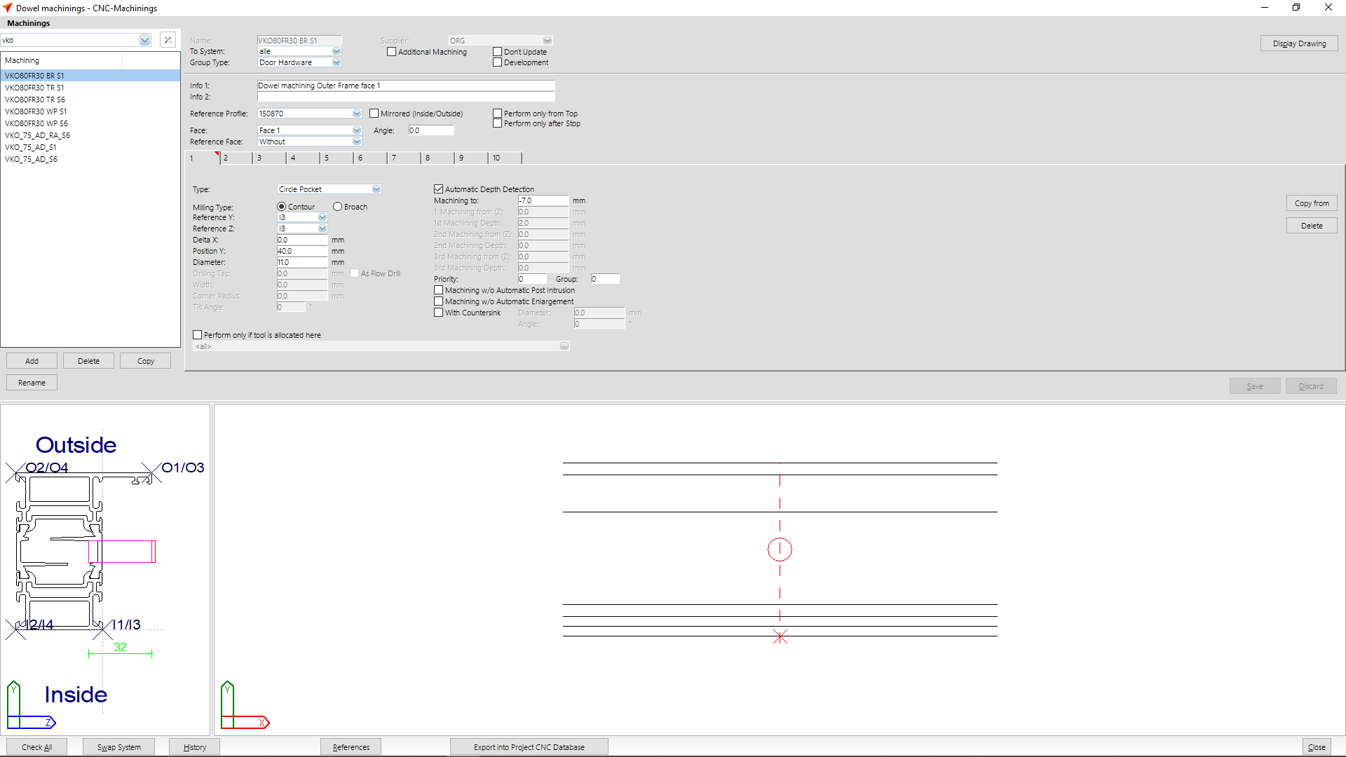
Enter the name of the machining at "Name". The CNC's list of abbreviations will show the most common abbreviations of machining names.
At "Group type" select the option "Door hardware".
Enter a description of the machining at Info 1 and 2.
At "Reference profile" you select the basic profile by which the machining is to be executed.
At „Face" select „Face 1"
At tab "1" you enter the following data:
- Type: Circle pocket
- Milling type: contour
- Reference Y: I3
- Reference Z: I3
- Delta X: 0,0
- Position Y: 40,0 mm
- Diameter: 11,0 mm
- Activate „Automatic Depth Detection"
- Machining to: -7,0 mm
After you have entered the data, click on the "Save" button.
In the preview below you can see the result of your input and if necessary you can correct it.
Anchor machining door frame face 1
The second step is to create the machining for a door frame on face 1.
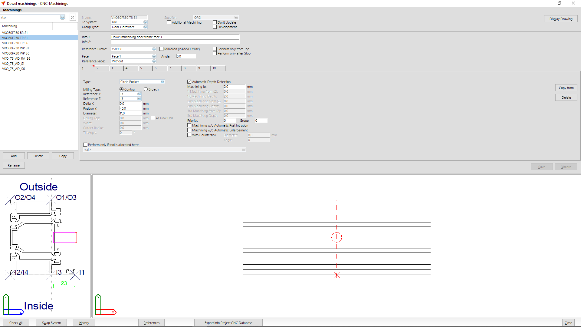
Enter the name of the machining at "Name". The CNC's list of abbreviations will show the most common abbreviations of machining names.
At "Group type" select the option "Door hardware".
Enter a description of the machining at Info 1 and 2.
At "Reference profile" you select the basic profile by which the machining is to be executed.
At „Face" select „Face 1"
At tab "1" you enter the following data:
- Type: Circle pocket
- Milling type: contour
- Reference Y: I3
- Reference Z: I3
- Delta X: 0,0
- Position Y: 40,0 mm
- Diameter: 11,0 mm
- Activate „Automatic Depth Detection"
- Machining to: 2,0 mm
After you have entered the data, click on the "Save" button.
In the preview below you can see the result of your input and if necessary you can correct it.
Anchor machining door frame face 6
The third step is to create the machining for a door frame on face 6.
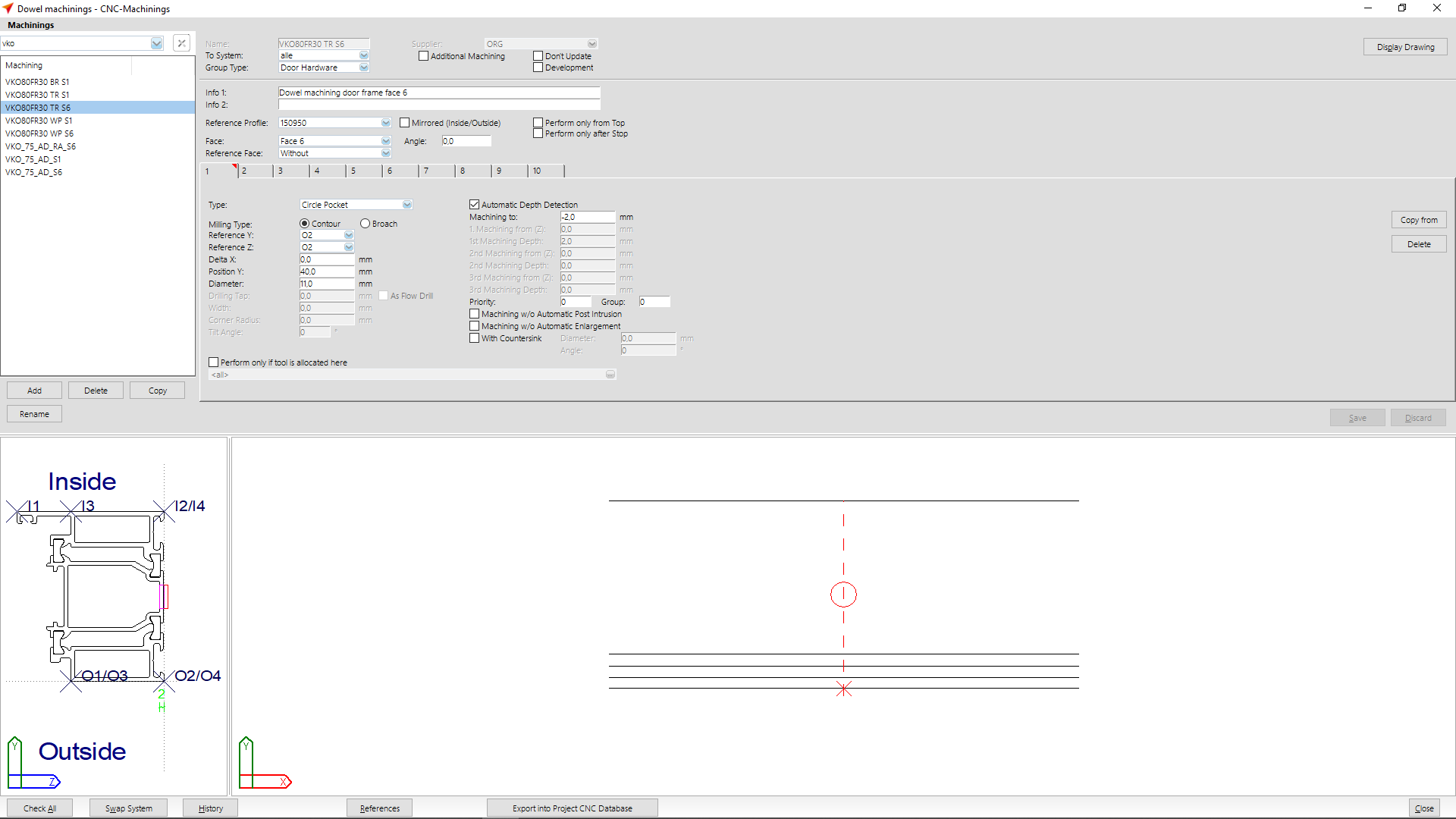
Enter the name of the machining at " Name". The CNC's list of abbreviations will show the most common abbreviations of machining names.
At "Group type" select the option "Door hardware".
Enter a description of the machining at Info 1 and 2.
At "Reference profile" you select the basic profile by which the machining is to be executed.
At „Face" select „Face 6"
At tab "1" you enter the following data:
- Type: Circle pocket
- Milling type: contour
- Reference Y: A2
- Reference Z: A2
- Delta X: 0,0
- Position Y: 40,0 mm
- Diameter: 11,0 mm
- Activate „Automatic Depth Detection"
- Machining to: -2,0 mm
After you have entered the data, click on the "Save" button.
In the preview below you can see the result of your input and if necessary you can correct it.
Anchor machining reverse rebate profile face 1
The fourth step is to create the machining for a reverse rebate profile on face 1.
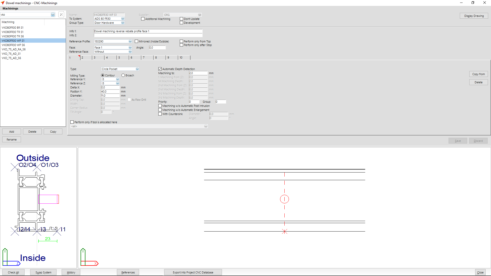
Enter the name of the machining at "Name". The CNC's list of abbreviations will show the most common abbreviations of machining names.
At "Group type" select the option "Door hardware".
Enter a description of the machining at Info 1 and 2.
At "Reference profile" you select the basic profile by which the machining is to be executed.
At „Face" select „Face 1"
At tab "1" you enter the following data:
- Type: Circle pocket
- Milling type: contour
- Reference Y: I3
- Reference Z: I3
- Delta X: 0,0
- Position Y: 40,0 mm
- Diameter: 11,0 mm
- Activate „Automatic Depth Detection"
- Machining to: 2,0 mm
After you have entered the data, click on the "Save" button.
In the preview below you can see the result of your input and if necessary you can correct it.
Anchor machining reverse rebate profile face 6
The fifth step is to create the machining for a reverse rebate profile on face 6.

Enter the name of the machining at "Name". The CNC's list of abbreviations will show the most common abbreviations of machining names.
At "Group type" select the option "Door hardware".
Enter a description of the machining at Info 1 and 2.
At "Reference profile" you select the basic profile by which the machining is to be executed.
At „Face" select „Face 6"
At tab "1" you enter the following data:
- Type: Circle pocket
- Milling type: contour
- Reference Y: A2
- Reference Z: A2
- Delta X: 0,0
- Position Y: 40,0 mm
- Diameter: 11,0 mm
- Activate „Automatic Depth Detection"
- Machining to: -5,4 mm
After you have entered the data, click on the "Save" button.
In the preview below you can see the result of your input and if necessary you can correct it.
Group machinings
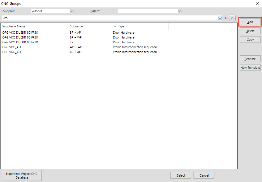
Select at "CNC Database" > "CNC Groups".

Click the "Add" button to create a new group.
Group for outer door frames
Enter the main group name at "Name".
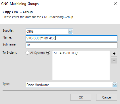
At "Subname" you enter the more detailed name for the group.
In this example TR.
TR = Door frame
Determine the system in which the machining group is to be used and select the option "Door hardware" under „Type".
Click "OK".
In the next window, you define the profiles and machinings to be used in this group.
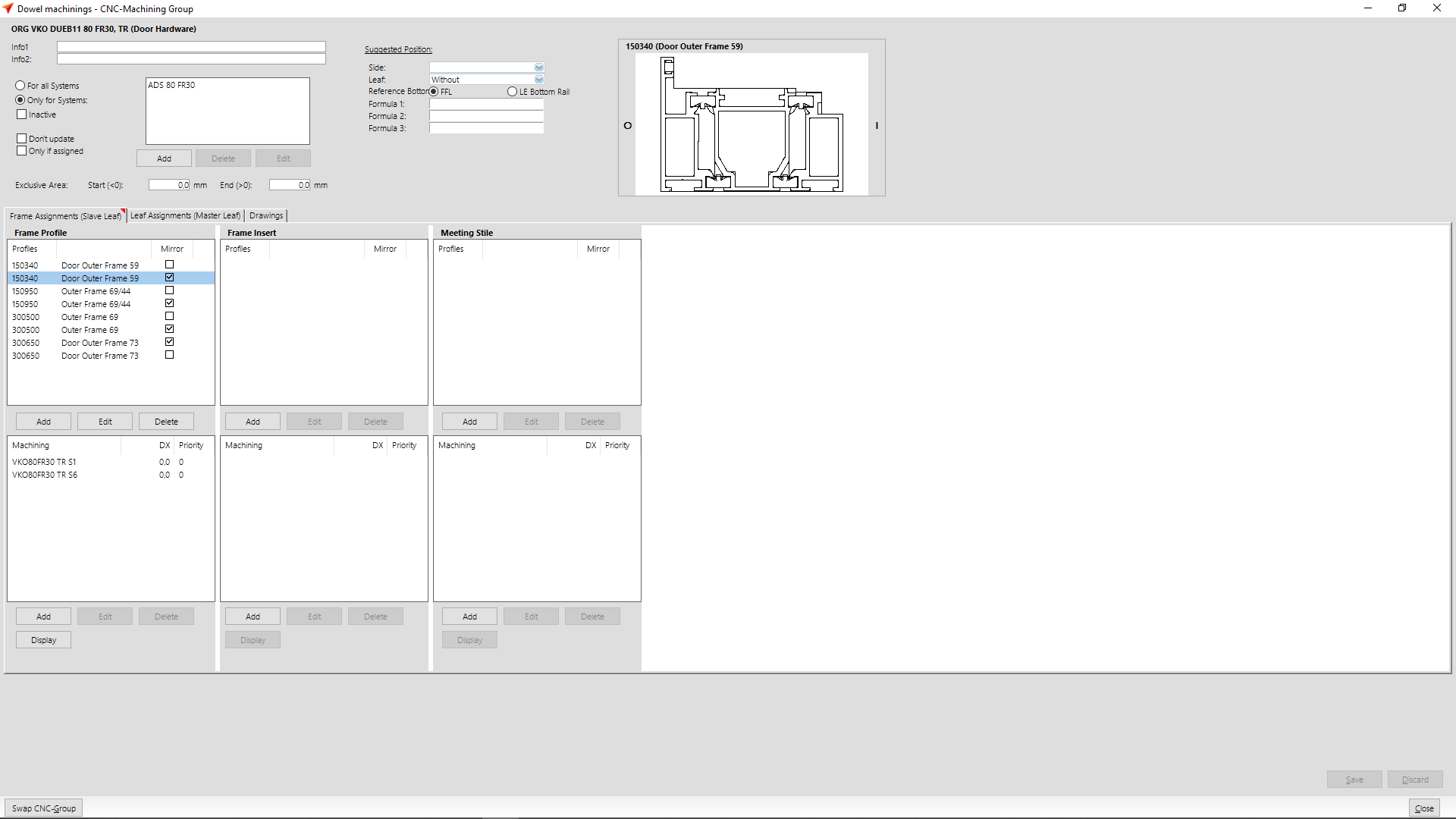
In the section "Frame profile" you enter the profile numbers for which the machinings are to be considered. In the input area below, enter the machinings that you have created for this purpose.
In the section "Frame insert" you enter the profiles that can occur in combination with the frame profile.
Group for outer frame and adapter profile
Note: Adapter profiles can be entered in the clamping positions when they are laid on. In this case, you do not need to create any further machinings for these profiles. If you edit stop sides individually, machinings are required.
Select at "CNC Database" > "CNC Groups".
Click the "Add" button to create a new group.

Select the supplier.
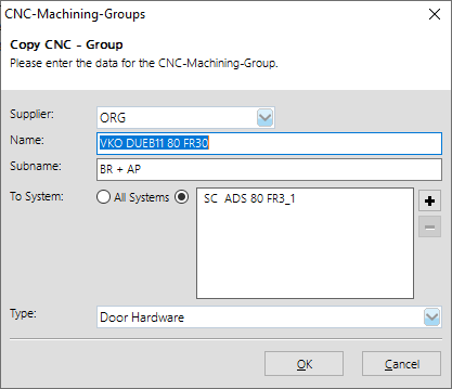
Enter the main group name at "Name".
At "Subname" you enter the more detailed name for the group.
Here in this example BR + AP.
BR = Outer frame
AP = Adapter profile
Determine the system in which the machining group is to be used and select the option "Door hardware" at "Type".
Click on "OK".
In the next window, you define the profiles and machinings to be used in this group.
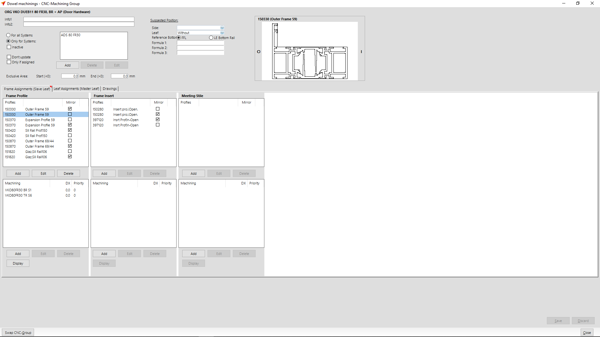
In the section "Frame profile" you enter the profile numbers for which the machinings are to be considered. In the input area below, enter the machinings that you have created for this purpose.
In the section "Frame insert" you enter the profiles that can occur in combination with the frame profile.
Group for outer frames and reverse rebate profiles
Create a new CNC group.

Enter the main group name at "Name".
At "Subname" you enter the more detailed name for the group.
Here in this example BR + WP.
BR = Outer frame profile
WP = Reverse rebate profile
Determine the system in which the machining group is to be used and select the option "Door hardware" at "Type".
Click on "OK".
In the next window, you define the profiles and machinings to be used in this group.
Note: Reverse rebate profiles cannot be entered as "attached only" in the clamping positions.
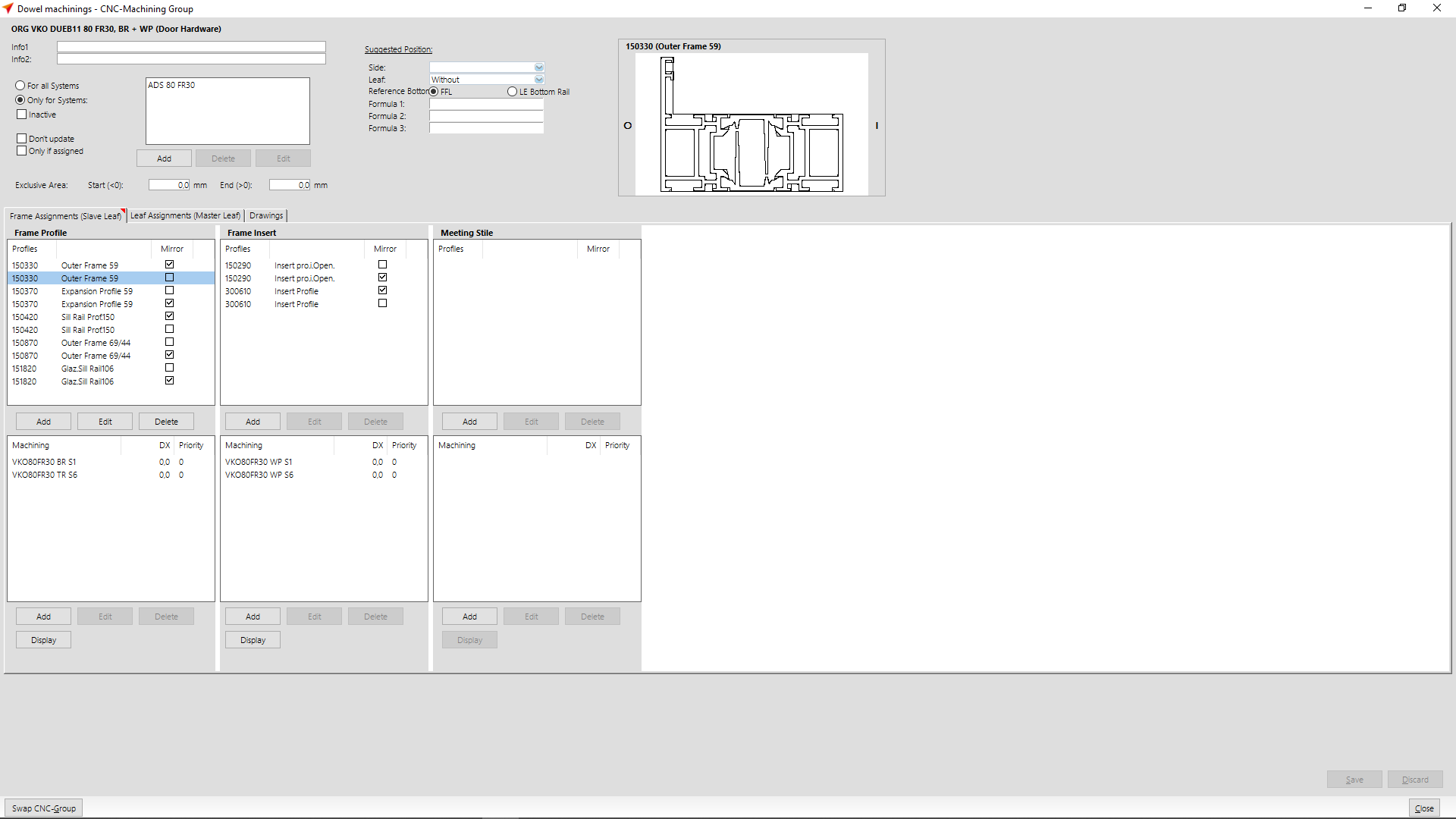
In the section "Frame profile" you enter the profile numbers for which the machinings are to be considered. In the input area below, enter the machinings that you have created for this purpose.
In the section "Frame insert" you enter the profiles that can occur in combination with the outer frame profile. In the input area below, you enter the machinings to be considered for these profiles.
Create hardware macro
To ensure that the CNC groups are taken into account in the input of elements, enter them under "User Database" > "Macro" > "Hardware".
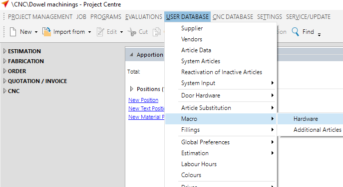
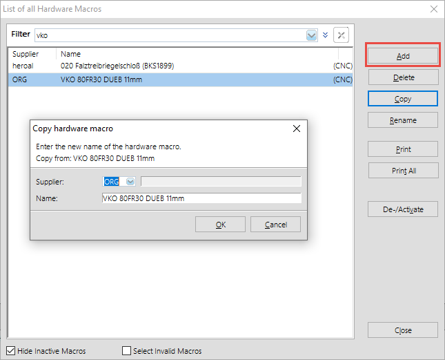
Create a new hardware macro by clicking on the "Add" button.
Select the supplier and define a name for the hardware macro.
In the next step, enter the CNC assignment for the groups.
To do this, click on the "Add" button at the left bottom.
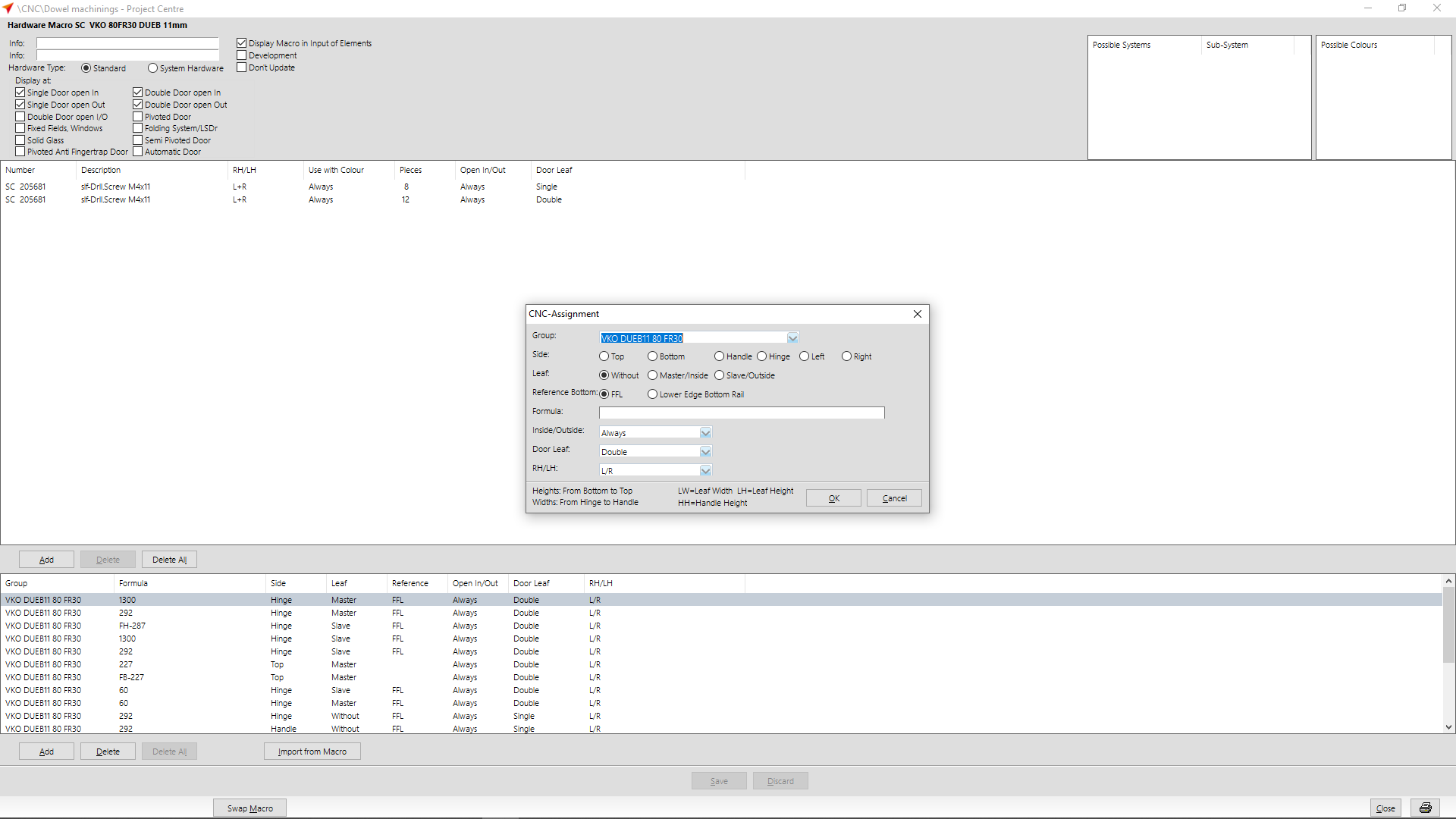
Choose the appropriate group.

Determine at "Face" whether the machining is to be considered at the top, bottom, left, right or on the handle or hinge side.
At "Leaf" you define the leaf type for which the hardware macro is to be used. (Further information can also be found at the description "door leaf" below).
At "Reference Bottom" select either "FFL" or " lower edge bottom rail".
Enter the formula.
At "Inside/Outside" you select whether the hardware macro is always displayed or only inside or only outside.
At "Door leaf" you select the leaf type for anchor machining. You can choose between "single" or "double" leaf. Please note that in the case of a double-wing door, you must enter if it is a fixed or moving leaf at "Leaf".
At "RH/LH" you define the opening direction. You can choose between "L/R", "DIN L" and "DIN R".
Proceed in the same way for the other anchor settings.
You can see a sample overview of the individual formulas here:

After you have provided the groups with formulas, you can enter additional screws in the upper area. The number of screws always refers to the number of machinings that you have created in the lower area.
Click on the "Add" button above the group assignment.
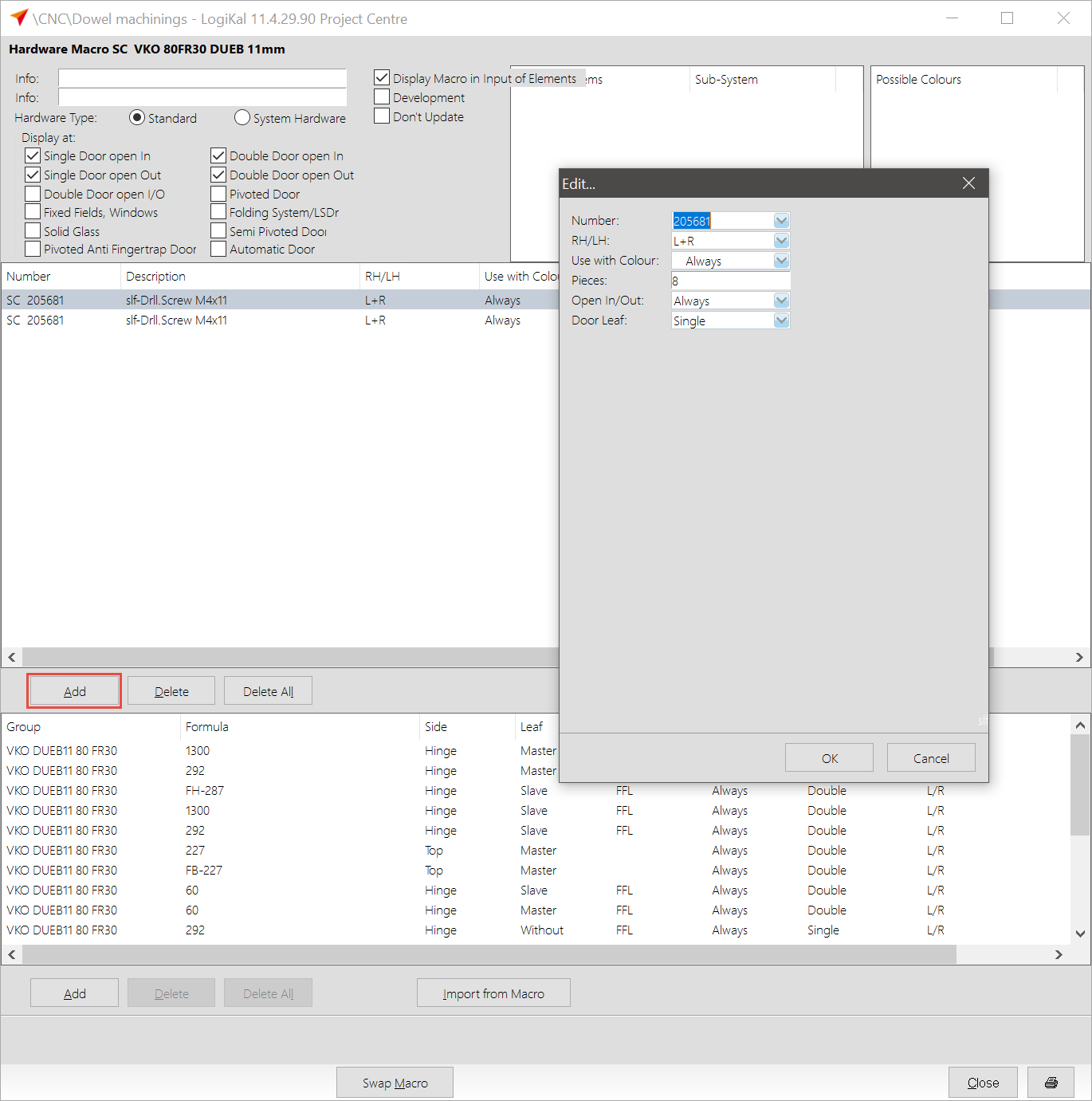
In the following window, enter the article number of the screw at "Number".
At "RH/LH" you define the opening direction. You can choose between "L/R", "DIN L" and "DIN R".
Below this you enter the colours for which this article is to be used.
At "Open in/out" you can choose whether the screws should always be used or only inside or only outside.
For "Door leaf" you select the type of leaf for which the screws can be used. You can choose between "Always", "Single" or "Double" leaf.
Use in input of elements
In the input of elements, switch to the „Hardware" area.
In the lower area at "Additional hardware", click on the right mouse button and select the option "New" from the context menu.
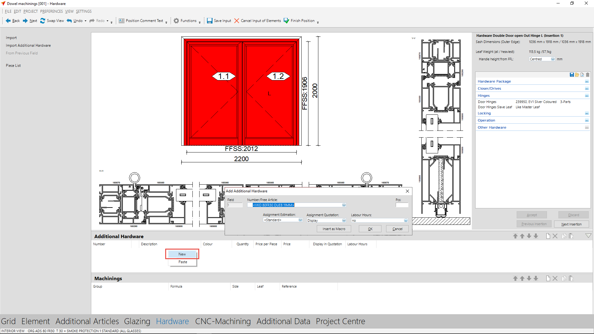
Note: Hardware macros are displayed in black font if the profiles are stored in the CNC groups and are also available in the position. If the font is grey, the selected profiles are not stored in the CNC group. If necessary, add the profiles to the CNC group or select other profiles in the input of elements.
At "Number/free article" select the screws you have defined in the hardware macro. Click on "OK".
If you make subsequent changes in the hardware macro, delete the old hardware macro from the input of elements and insert the new hardware macro with the changes.
Underneath "Machinings" the individual machinings from the hardware macro are now listed, which are used in this position.

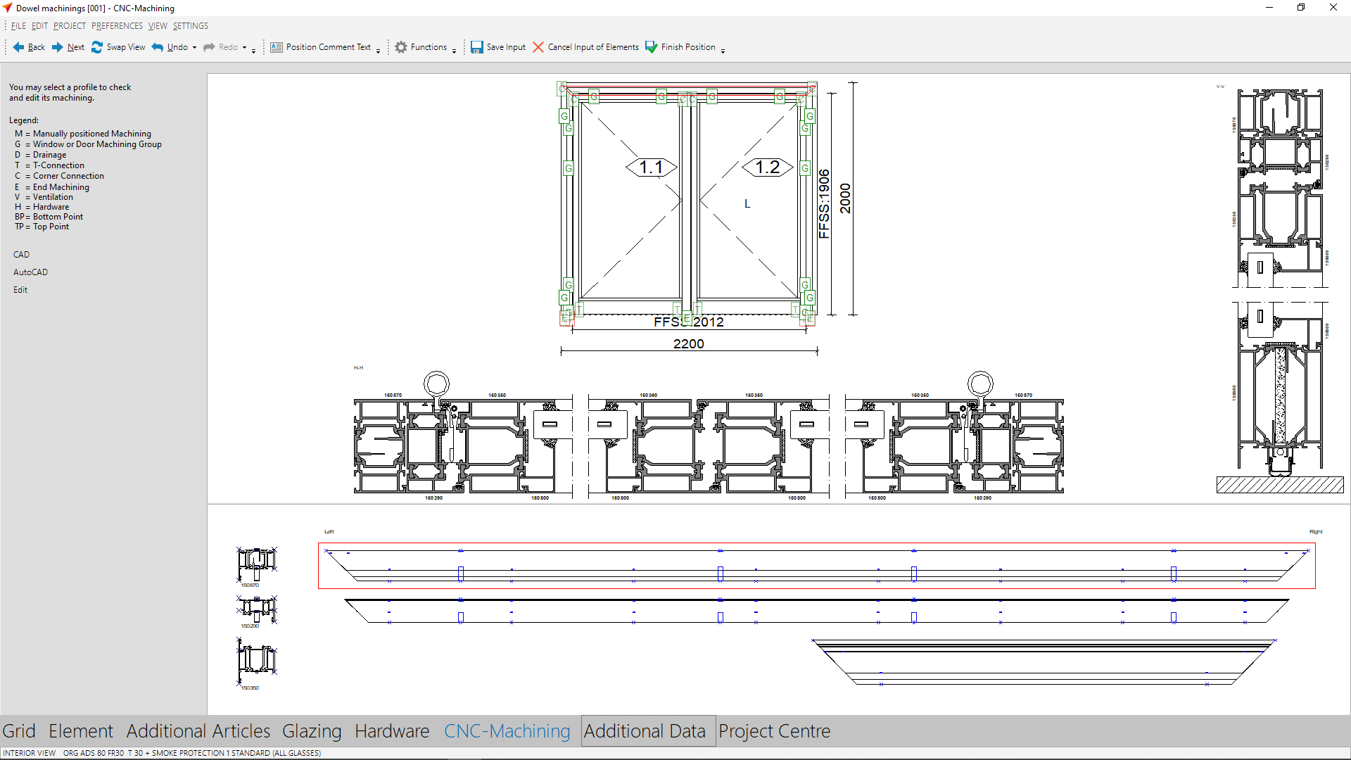
In the section "CNC-Machining" the machinings are displayed in the bar drawings.


 English (UK)