Literally making a good cut with the completely revised cross section. The program has been designed even more user friendly and furthermore remembers all alterations you carry out – also in other program parts, such as printouts.
Section Drawings are saved
The start and end point of the section line, as well as the positioning of all drawing entries in the plot menu, are saved automatically for each position and are always available the next time you open the section drawing.
Automatic Cross Display in the Cross Section
The settings to horizontal and vertical sections from the input of elements serve as basis for automatically generated sections, when asking for the cross section.
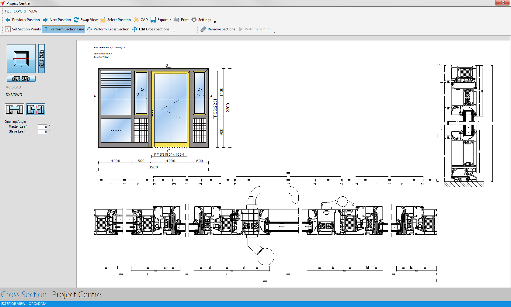
Subsequent Changes of Sections
The section lines and section drawings can be modified subsequently. You can influence the position and the alignment of the section lines. In case you have assigned further side fields to an element e.g. you can lengthen the already existing section very easily and thus include the new fields into the section, without having to create the whole section drawing again. You determine the exact display of the cut elements directly in the section output.
Activate the function "Edit Cross Sections" in the toolbar.

The position drawing will show control points displayed as small, grey boxes, for each section line now.
With these control points and by keeping the left mouse button pushed, you can shorten or lengthen the section lines, or move the section line in its whole position. The section drawings will be adjusted automatically.
Section Printouts with Interior and Exterior View
You can display interior and exterior view on one page.
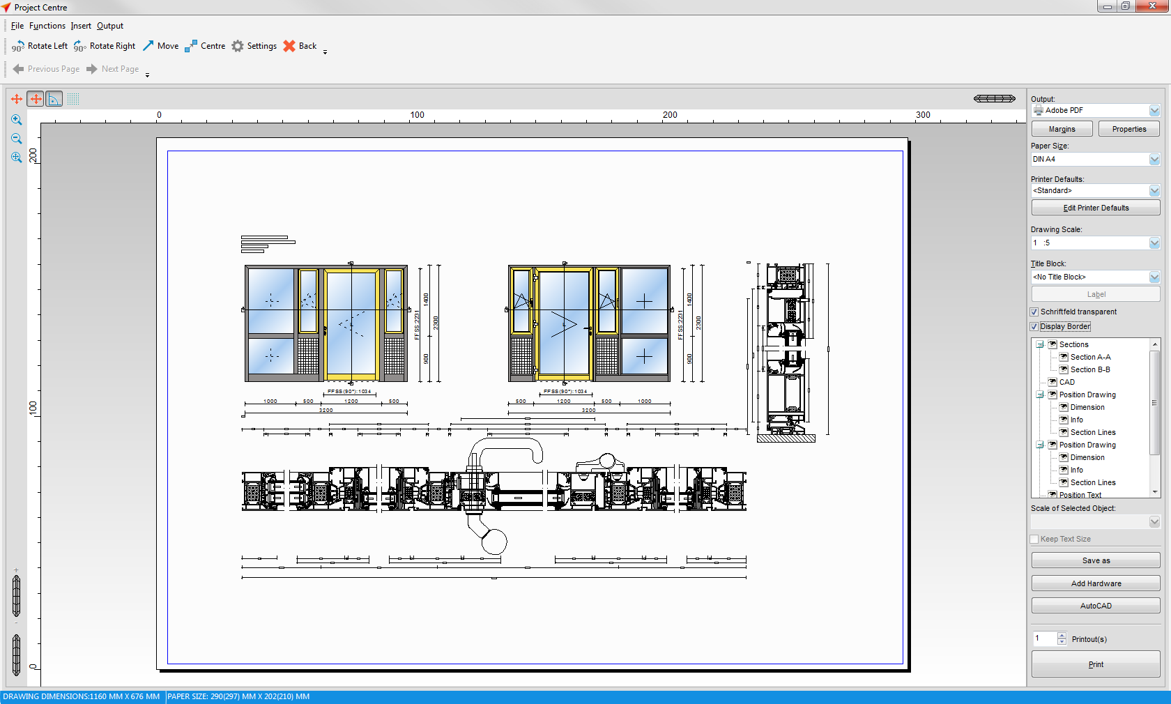
Click "Settings" → "Cross Section" in the project centre's file menu and activate the option "Interior and Exterior View" under "Printout" left down below.

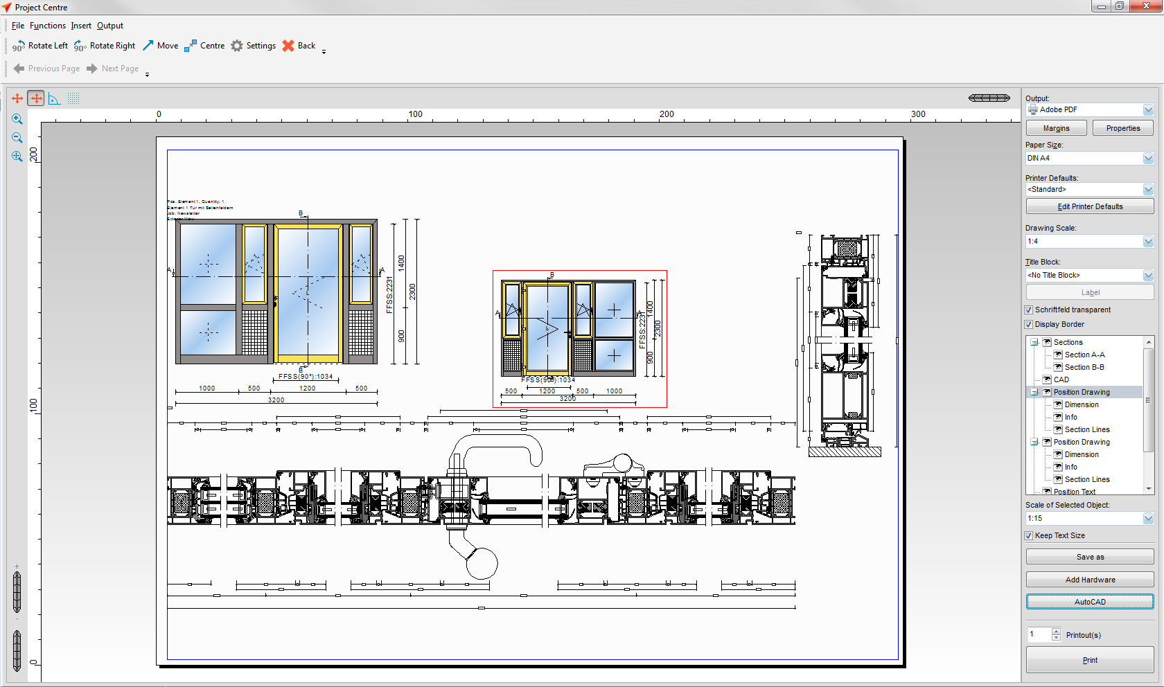
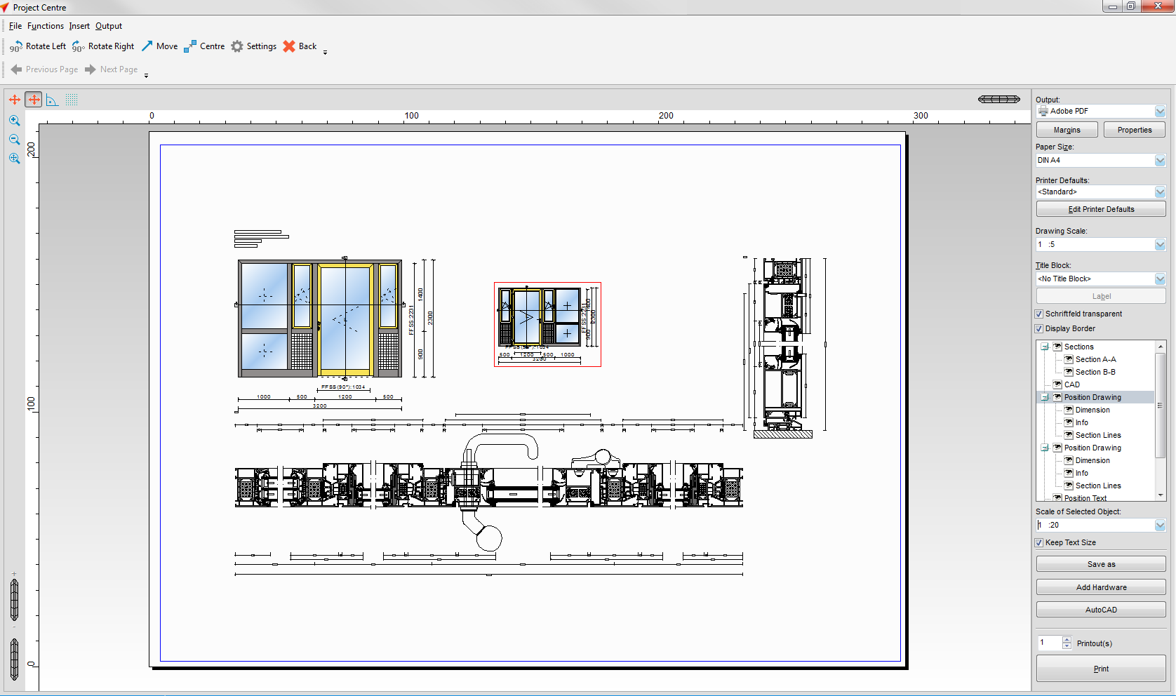
Free Design of Drawings on the Printout
You can position each individual drawing element freely or depending on other elements. Furthermore you can assign an own scale to each drawing element and thereby enlargen or reduce the display.
With that, a lot of additional drawing work and manual adjustments of plans in CAD can be saved.
Mark one or several drawing elements – while pushing the Ctrl key – and move them to the requested area of the plan by using the mouse. For an exact positioning several aids are available.
On the one hand you can determine the direction to "Rectangular Drawing", so that the drawing elements can only be moved horizontally or vertically on the plan and the original alignment remains unchanged. Activate the according symbol in the upper hand corner.
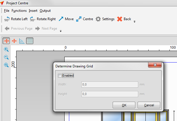
On the other hand you can insert your own grid, which allows for a very flexible yet arranged layout of elements.
Just as easily you can assign your own scale to all drawing elements independently. Mark the element and set the scale under "Scale of Element".


 English (UK)